Device, system, and method for forming a cavity in and delivering a curable material into bone

a technology of stabilizing material and bone structure, applied in the field of devices and methods for stabilizing bone structure, can solve the problems of affecting the surgeon's ability to infuse all desired areas, the surgical site in question cannot be fully accessed using a conventional, straight needle cannula, and the risk of coring tissue with needle cannula, so as to reduce the risk of coring tissue or reduce the operating room time

Active Publication Date: 2010-05-13
STRYKER CORP
View PDF67 Cites 19 Cited by
  • Summary
  • Abstract
  • Description
  • Claims
  • Application Information

AI Technical Summary

Benefits of technology

[0011]Benefits achieved in accordance with principles of the disclosed invention include a delivery cannula providing a non-traumatic, blunt distal end that minimizes the risks of coring tissue or puncturing bone or tissue during intraosseous procedures without requiring additional components (such as separate wire). Other benefits relate to a delivery cannula defining at least one side orifice adjacent to a blunt distal end, where the orifice(s) permit a radial infusion of a curable material at a site within bone even in the case where the distal end is in contact with bone and / or tissue. Thus, a palliative bone procedure can be accomplished with reduced operating room time and with fewer approaches of surgical instruments to the bone site. For example, unipedicular vertebroplasty is readily accomplished. Further, virtually any area within the surgical site can be accessed. Also, the distal end of the delivery cannula can be placed as close as desired to a particular anatomical feature of the surgical site (e.g., a bone fracture) without fear that subsequently delivered material will forcibly progress into or through that feature.
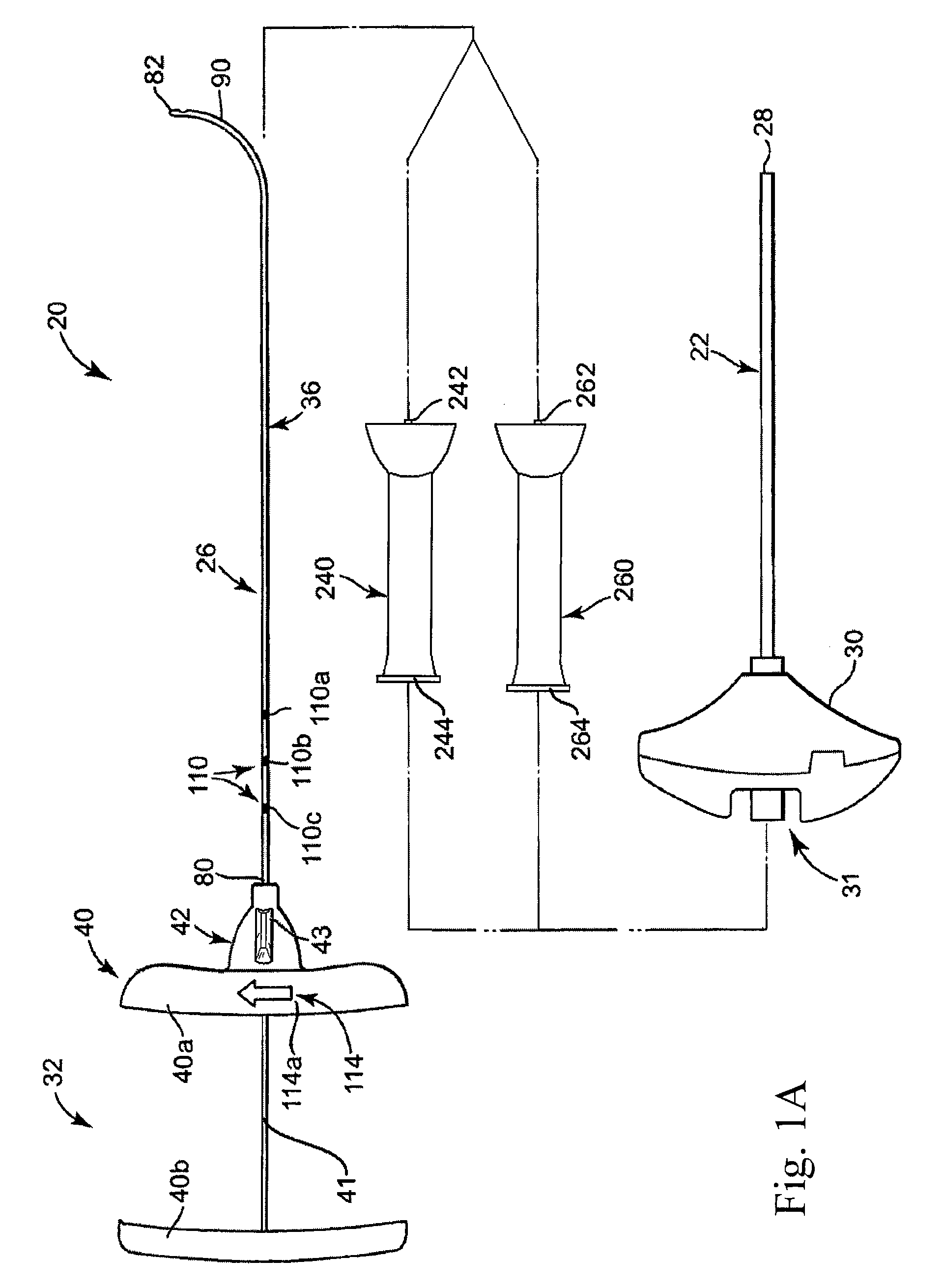
[0012]Other benefits achieved in accordance with principles of the disclosed invention include a curved needle with sufficient strength to allow it to be used for creating a void in cancellous bone tissue to enhance introduction of a palliative material (e.g., curable bone cement material). Other benefits include one or more spacers that may be used to control the size and location of a void being created by controlling the depth and exposed curvature of a needle within, for example, a vertebral body.
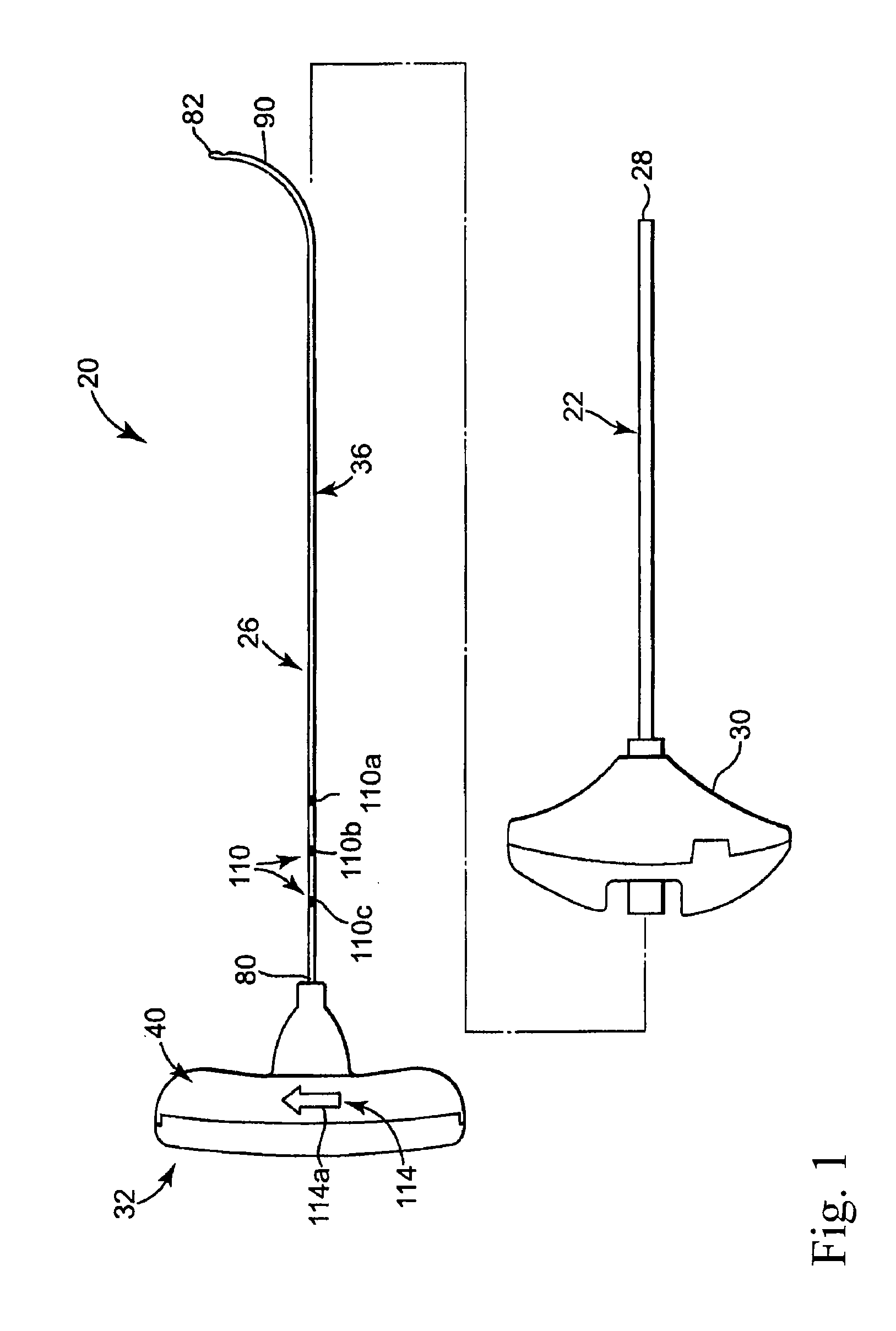
[0013]Some aspects of the present invention relate to a delivery cannula device for delivering a curable material into bone. The device includes a delivery cannula and a hub forming a fluid port. The delivery cannula defines a proximal end, a deflectable segment, a distal end, a lumen, and at least one side orifice. The proximal end is axially open to the lumen. The deflectable segment is formed opposite the proximal end and terminates at the distal end that is otherwise axially closed. Further, the distal end has a blunt tip. The lumen extends from the proximal end and is fluidly connected to the side orifice(s). To this end, the side orifice(s) is formed adjacent to, and proximally space from, the distal end. Finally, the deflectable segment forms a curved shape in longitudinal extension and has a shape memory characteristic. With this configuration, the deflectable segment can be forced to a substantially straightened shape and will revert to the curved shape upon removal of the force. The hub is fluidly coupled to the proximal end of the delivery catheter. With this construction and during use, the distal end will not damage or core tissue when inserted into a delivery site within bone due to the blunt tip. Further, the side orifice(s) afford the ability to inject a curable material regardless of whether the distal end is lodged against bodily material, and can achieve more thorough dispensing.
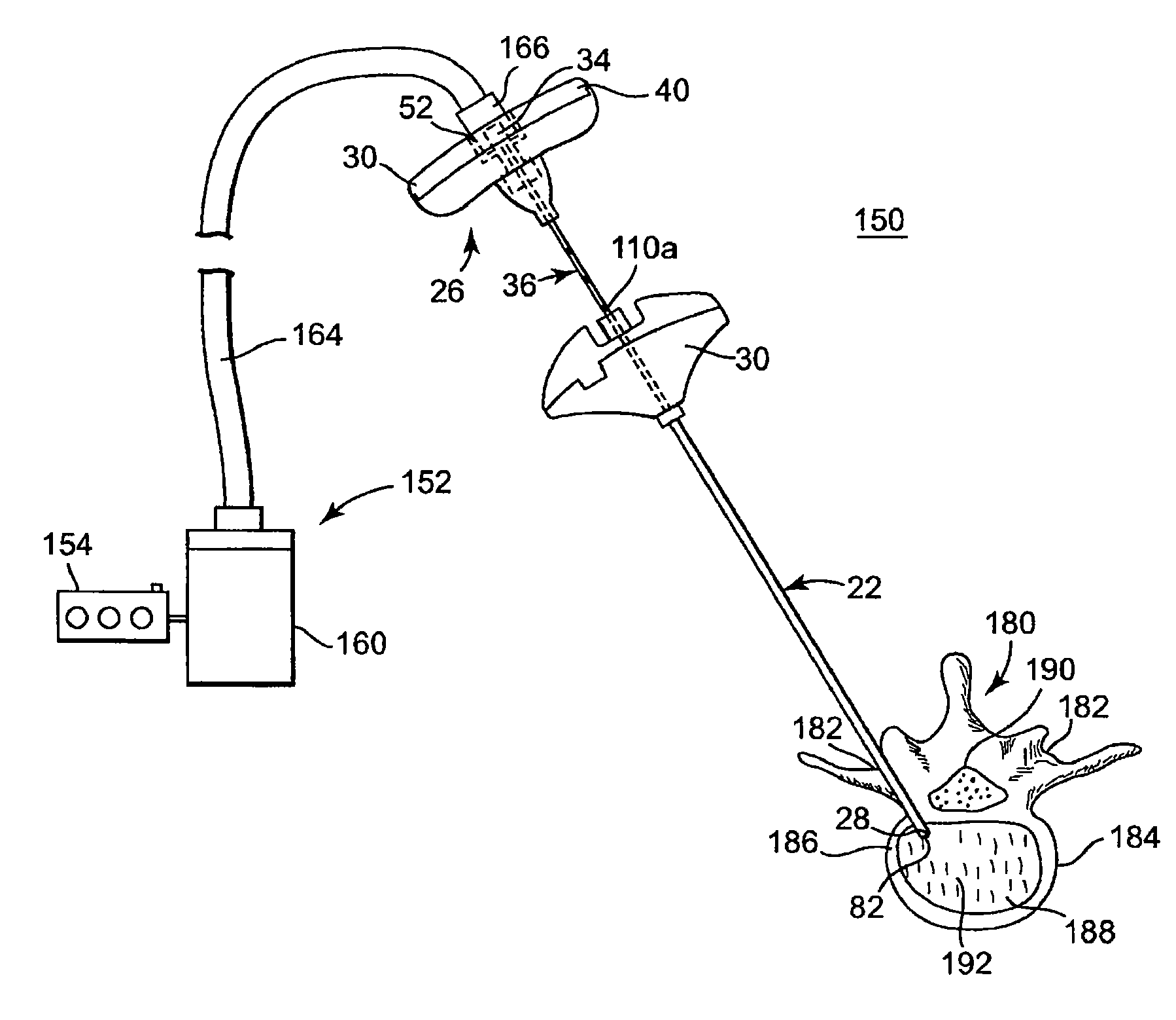
[0015]Yet other aspects of the present invention relate to a method of stabilizing a bone structure of a human patient. The method includes providing a delivery cannula as previously described. A distal tip of a guide cannula is located within the bone structure. The delivery cannula is inserted within the guide cannula. In this regard, the deflectable segment deflects to a substantially straightened shape within the guide cannula. The delivery cannula is distally advanced relative to the guide cannula such that the distal end and at least a portion of the deflectable segment of the delivery cannula projects distal the distal tip of the guide cannula. To this end, the portion of the deflectable segment distal the distal tip of the guide cannula naturally reverts to the curved shape. The distal end of the delivery cannula is positioned adjacent a desired delivery site within the bone structure. A curable material is injected into the lumen. The injected curable material is delivered to the delivery site via the side orifice(s). Once delivered, the curable material is allowed to cure so as to stabilize the bone structure. In one embodiment, the method further includes rotating the delivery cannula relative to the guide cannula so as to alter a spatial position of the side orifice(s), thus affording the ability to inject the curable material in different planes.
[0017]Yet another aspect of the present invention relates to a method of injecting curable material to a delivery site within a bone structure. The method includes the step of providing a delivery cannula having an open, proximal end, a deflectable segment opposite the proximal end having a distal end and a lumen extending from the proximal end. The deflectable segment has a shape memory characteristic and naturally assumes a curved shape in longitudinal extension. In the method, the distal tip of a guide cannula is located within the bone structure. The delivery cannula is inserted within the guide cannula, characterized by the deflectable segment deflecting to a substantially straightened shape within the guide cannula. The delivery cannula is distally advanced such that the distal end and at least a portion of the deflectable segment projects distal the distal tip, characterized by the portion of the deflectable segment distal the distal tip naturally reverting to the curved shape. The distal end is positioned distally adjacent a first region within the delivery site. The curable material is then delivered to the first region within the delivery site. The distal end is then positioned adjacent a second region within the delivery site and curable material is delivered to the second region within the delivery site. Using one or more spacers may provide positional control and accuracy of delivery to a plurality of desired regions within a delivery site.

Problems solved by technology

With the above in mind, because the needle cannula interacts with the cancellous bone and other soft tissue structures, an inherent risk exists that following initial insertion, the needle cannula might core or puncture other tissue and / or the bone mass being repaired (at a location apart from the insertion site).
Unfortunately, for many procedures, the surgical site in question cannot be fully accessed using a conventional, straight needle cannula.
Further, the needle can only dispense the stabilizing material through the axial opening at the distal tip of the needle, perhaps impeding a surgeon's ability to infuse all desired areas and / or requiring an additional procedural step of “backing” the needle tip away from the desired delivery site.
Also, because the needle tip, and thus the axial opening, is likely at or facing the bone defect (e.g., fracture in the vertebral body) being repaired, the stabilizing material may be injected directly at the defect, giving rise to a distinct possibility that the stabilizing material will forcibly progress through and outwardly from the defect.
This is clearly undesirable.
The issues and concerns described above in the context of percutaneous vertebroplasty can also arise in similar surgical procedures at other bone sites.
However, the known access and infusion techniques necessitate multiple needle sticks and / or risk coring bone or tissue.

Method used


Image

  • Device, system, and method for forming a cavity in and delivering a curable material into bone
  • Device, system, and method for forming a cavity in and delivering a curable material into bone
  • Device, system, and method for forming a cavity in and delivering a curable material into bone

Examples


Embodiment Construction

[0049]FIG. 1 illustrates components of one embodiment of an intraosseous, curable material delivery system 20. The system 20 includes an outer guide cannula 22 and a delivery cannula device 26 (referenced generally). Details on the various components are provided below. In general terms, however, a portion of the delivery cannula device 26 is sized to be slidably disposed within the guide cannula 22 that otherwise serves to form and / or locate a desired delivery site within bone. Once positioned, the delivery cannula device 26 is employed to inject a curable, bone stabilizing material into the delivery site. The system 20 can be used for a number of different procedures, including, for example, vertebroplasty and other bone augmentation procedures in which curable material is delivered to a site within bone, as well as to remove or aspirate material from a site within bone.

[0050]The system 20, and in particular the delivery cannula device 26, is highly useful for delivering a curable...


PUM


Abstract

A curable material delivery cannula device is disclosed. The device includes a cannula and a hub. The cannula includes an open proximal end, a deflectable segment forming a pre-set curve, a lumen, and side orifice(s) adjacent, and proximally spaced from, the distal end and fluidly connected to the lumen. When inserted within a guide cannula, the deflectable segment straightens. When distally extended from the guide cannula, the deflectable segment reverts to the curved shape. The distal end has a blunt tip for non-traumatic interface with bodily material. During use, curable material, such as bone cement, is delivered from the side orifice(s) in a radial direction relative to the lumen. The device may be used to create voids for receiving curable material, and may include spacers configured to control location and / or orientation of the voids.

Description

RELATED APPLICATIONS[0001]This application is a continuation-in-part of pending U.S. patent application Ser. No. 11 / 704,139, entitled “Device, System and Method for Delivering a Curable Material Into Bone,” filed Feb. 8, 2007, which is a continuation-in-part of U.S. patent application Ser. No. 11 / 282,102, entitled “Device, System and Method for Delivering a Curable Material Into Bone,” filed Nov. 18, 2005, each of which is herein incorporated by reference in its entirety.BACKGROUND[0002]The present invention relates to devices and methods for stabilizing bone structures. More particularly, it relates to devices, systems and methods for delivering a curable, stabilizing material into a bone structure.[0003]Surgical intervention at damaged or compromised bone sites has proven highly beneficial for patients, for example patients with back pain associated with vertebral damage.[0004]Bones of the human skeletal system include mineralized tissue that can generally be categorized into two ...

Claims


Application Information

Patent Timeline
Patent Type & Authority Applications(United States)
IPC IPC(8): A61B17/56A61M25/00
CPCA61B17/1604A61B17/1671A61B17/3421A61B17/3472A61B2019/462A61B17/8819A61B2017/00331A61B2017/00455A61B2017/00867A61B17/8811A61B2090/062
Inventor LINDERMAN, EVAN D.KRUEGER, JOHN A.
Owner STRYKER CORP
Why Eureka
Try Eureka