
Spiral cache power management, adaptive sizing and interface operations

a power management and adaptive sizing technology, applied in the field of cache memories, can solve the problems of increasing power consumption, performance degradation, and the speed at which power management operations can be performed is necessarily slow relative to the rate of data flow

Inactive Publication Date: 2010-05-13
IBM CORP
View PDF8 Cites 44 Cited by
  • Summary
  • Abstract
  • Description
  • Claims
  • Application Information

AI Technical Summary

Benefits of technology

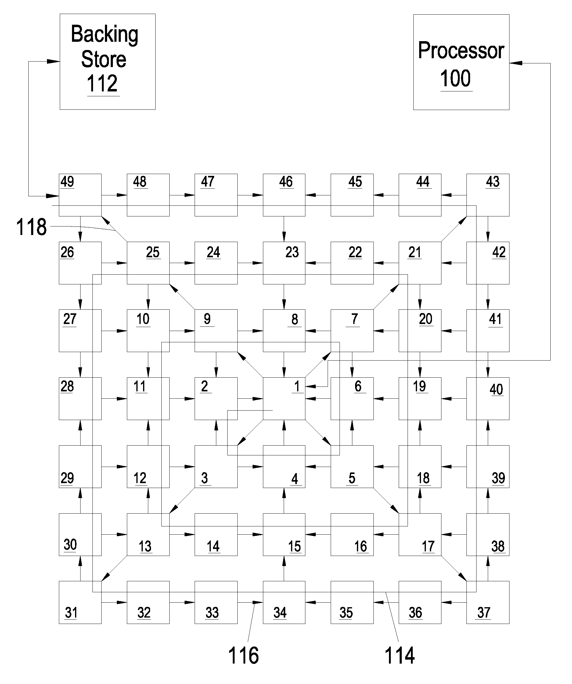
[0011]Requested values are always provided at an interface to a front-most tile, which are satisfied from the cache itself or a higher-order level of a memory hierarchy that includes the cache. Storage locations are freed for storing the requested values if the cache is full by ejecting the values through a backing store interface. A buffer and flow control logic can be provided to prevent overflow of ejected values being written to the backing store. The spiral cache supports multiple outstanding requests, with no requirement that a value be returned to the front-most tile prior to another request being issued to the cache.

Problems solved by technology

However, due to physical wiring constraints and the fact that electronic systems are limited by the propagation speed of electronic signals, the larger the L1 cache, the longer the (fixed) access time for the typical L1 cache.
Also, the larger size of higher-order levels of a memory hierarchy leads to increased power consumption, and while it is possible to partition a cache-memory into partitions that can be individually power-managed, such power management requires re-organization and movement of data between the partitions so that reducing the size of the cache does not compromise correctness or cause performance degradation.
Further, due to the need for re-organization in the cache, the speed at which power management operations can be performed is necessarily slow relative to the rate of data flow.
The alternative of stalling the entire processor pipeline is available, but provides an even more severe performance penalty.
Further, non-traditional cache memories have been proposed that have a non-uniform access latency and that are organized without using additional access measurement and cast-out logic, but generally only offer a small potential improvement over the operation of present cache memories by swapping cache entries to slowly migrate frequently accessed values to “closer” locations, while migrating less frequently used values to “farther” locations.
Such non-uniform cache memories also require additional pathways to perform the swapping and are typically routed systems, in which switching circuits are used to perform selection of a particular cache bank.

Method used


Image

  • Spiral cache power management, adaptive sizing and interface operations
  • Spiral cache power management, adaptive sizing and interface operations
  • Spiral cache power management, adaptive sizing and interface operations

Examples


Embodiment Construction

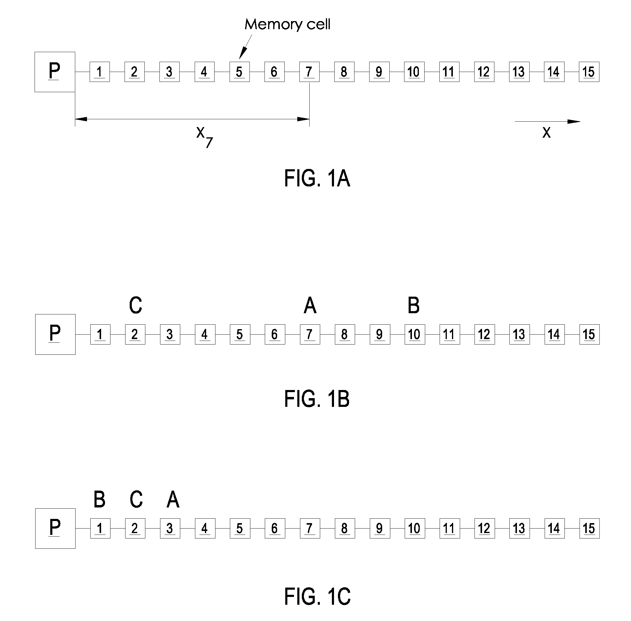
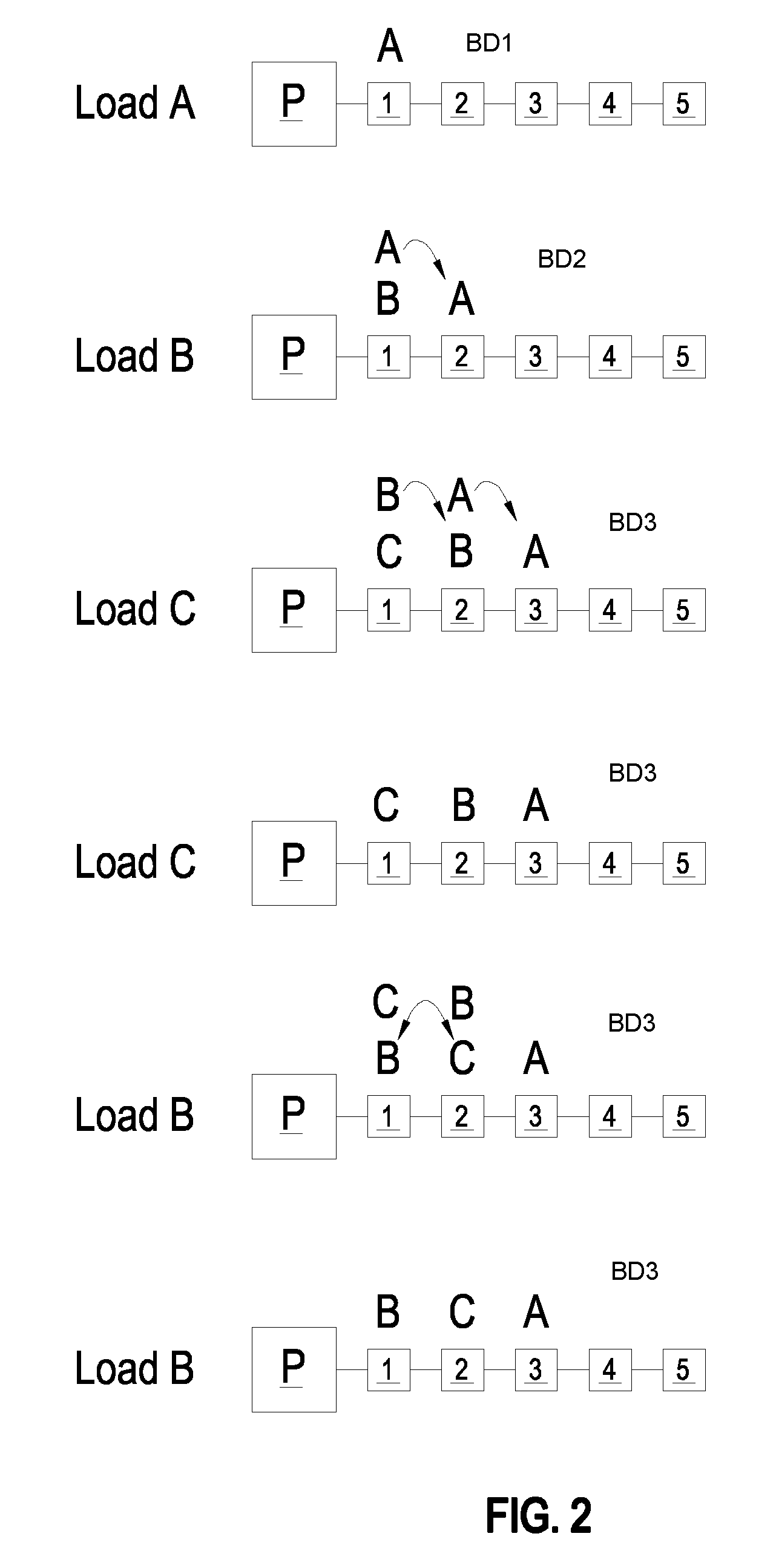
[0024]Introduction The present invention encompasses a memory circuit and method of operation that may be embodied in a cache memory structure that is structurally organized as a spiral and self-organizes its contents to place the most-recently accessed value at the front-most central storage location, while moving other values backwards at each access to a location other than the front-most central storage location. The resulting architecture provides a behavior according to an embodiment of the present invention, which provides each requested value at an interface to a front-most tile of a tiled structure, while making room for frequently requested values by ejecting less frequently requested values to a backing store. The spiral structure also enables power management that reduces power consumption of the memory circuit by partitioning the memory into an active and an inactive portion according to a boundary that may be adjusted on a per-tile basis. The fundamental principle unde...


PUM


Abstract

A spiral cache memory provides low access latency for frequently-accessed values by self-organizing to always move a requested value to a front-most storage tile of the spiral. If the spiral cache needs to eject a value to make space for a value moved to the front-most tile, space is made by ejecting a value from the cache to a backing store. A buffer along with flow control logic is used to prevent overflow of writes of ejected values to the generally slow backing store. The tiles in the spiral cache may be single storage locations or be organized as some form of cache memory such as direct-mapped or set-associative caches. Power consumption of the spiral cache can be reduced by dividing the cache into an active and inactive partition, which can be adjusted on a per-tile basis. Tile-generated or global power-down decisions can set the size of the partitions.

Description

[0001]The present Application is related to U.S. patent application Ser. No. 12 / ______, Attorney Docket Number AUS920080470US1, entitled “A SPIRAL CACHE MEMORY AND METHOD OF OPERATING A SPIRAL CACHE MEMORY” and filed contemporaneously herewith, U.S. patent application Ser. No. 12 / ______, Attorney Docket Number AUS920080471US1, entitled “TILED STORAGE ARRAY WITH SYSTOLIC MOVE-TO-FRONT REORGANIZATION” and filed contemporaneously herewith, and U.S. patent application Ser. No. 12 / ______, Attorney Docket Number AUS920080472US1, entitled “STORAGE ARRAY TILE SUPPORTING SYSTOLIC MOVEMENT OPERATIONS” and filed contemporaneously herewith, Each of the above-listed U.S. patent applications has at least one common inventor with the present application and is assigned to the same Assignee. The disclosures of all of the above-referenced U.S. patent applications are incorporated herein by reference.BACKGROUND OF THE INVENTION[0002]1. Field of the Invention[0003]The present invention is related to c...

Claims


Application Information

Patent Timeline
Patent Type & Authority Applications(United States)
IPC IPC(8): G06F12/08G06F12/00G06F1/32
CPCG06F12/0897G06F12/123Y02B60/1225G06F2212/271G06F2212/601G06F2212/1028Y02D10/00
Inventor STRUMPEN, VOLKERFRIGO, MATTEO
Owner IBM CORP
Learn More