Design of wet/wet differential pressure sensor based on microelectronic packaging process

a technology of microelectronic packaging and differential pressure sensor, applied in the direction of pressure difference measurement between multiple valves, instruments, liquid/fluent solid measurement, etc., can solve the problems of long-term reliability failure, damage to pressure sensor components, and usually corrosive or harmful effects

Active Publication Date: 2010-05-20
HONEYWELL INT INC
View PDF39 Cites 58 Cited by
  • Summary
  • Abstract
  • Description
  • Claims
  • Application Information

AI Technical Summary

Benefits of technology

[0010]It is another aspect of the present invention to provide for an improved topside cap differential pressure sensor with a hole that can overcome the aforementioned drawbacks.
[0013]A pair of pressure ports can be provided at the top and bottom of the package to allow the pressures to act on the pressure-sensing diaphragm. Sealing at the hole in the top cap provides protection by isolating wirebonds, wire bonding pads and other exposed circuitry from the sensed media. The diaphragm can be deformed in accordance with the pressure applied by the media. The deformation can be measured by piezoresistive elements doped on a surface of the diaphragm. The piezoresistive elements can convert the deformation of the diaphragm into electrical signals utilizing well-known piezoresistive principles in order to compute the pressure in the media. Adhesive and / or solder and / or elastomeric seal on either or both the top and bottom surfaces of the sense die can be utilized to achieve connections to a variety of pressure ports. Such a robust design solution for pressure sensing applications provides wet-wet media compatibility so that wet media comes into contact with both sides of the sensing diaphragm and not with other parts which may be damaged by exposure to the media.

Problems solved by technology

Hence the diaphragm of the differential pressure sensor can come into contact with the media that can be usually corrosive or harmful.
This corrosive or harmful media can damage components of the pressure sensors, in particular bond pads that are exposed electrical connection to the differential pressure sensor.
In many applications, even if the media itself is not electrically conducting it can create a harsh environment for the exposed bond pads, resulting in long-term reliability failures.
However there are very few cost effective solutions for a wet-wet pressure sensor.
Such pressure sensors can obtain a true differential operation and an accurate pressure of the media, but the increased production and material costs can be prohibitive.
Also, one problem which can be associated with such pressure sensors is thermal hysteresis associated with the elastomeric seals, which flex and move over temperature, thus causing shifts in the parametric performance of the device.

Method used


Image

  • Design of wet/wet differential pressure sensor based on microelectronic packaging process
  • Design of wet/wet differential pressure sensor based on microelectronic packaging process
  • Design of wet/wet differential pressure sensor based on microelectronic packaging process

Examples


Embodiment Construction

[0019]The particular values and configurations discussed in these non-limiting examples can be varied and are cited merely to illustrate at least one embodiment and are not intended to limit the scope thereof.

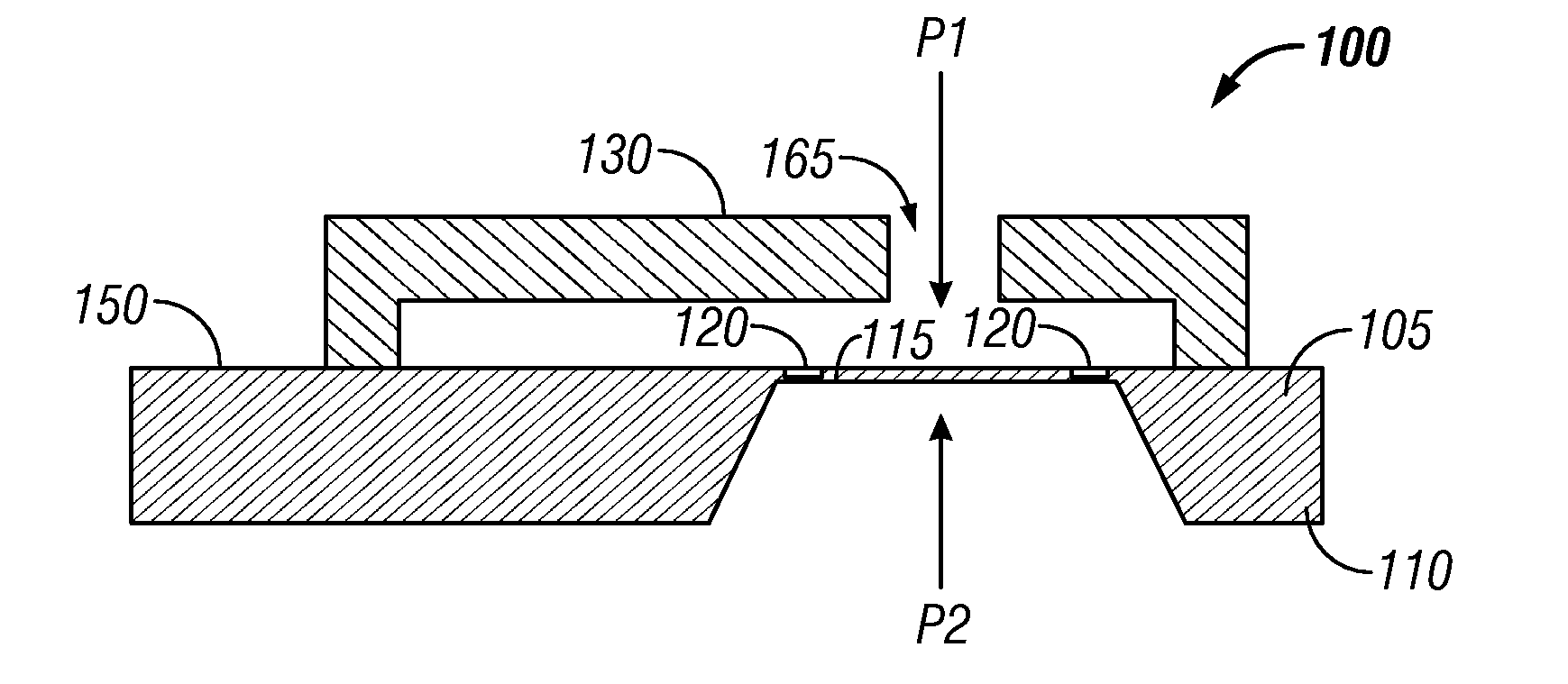
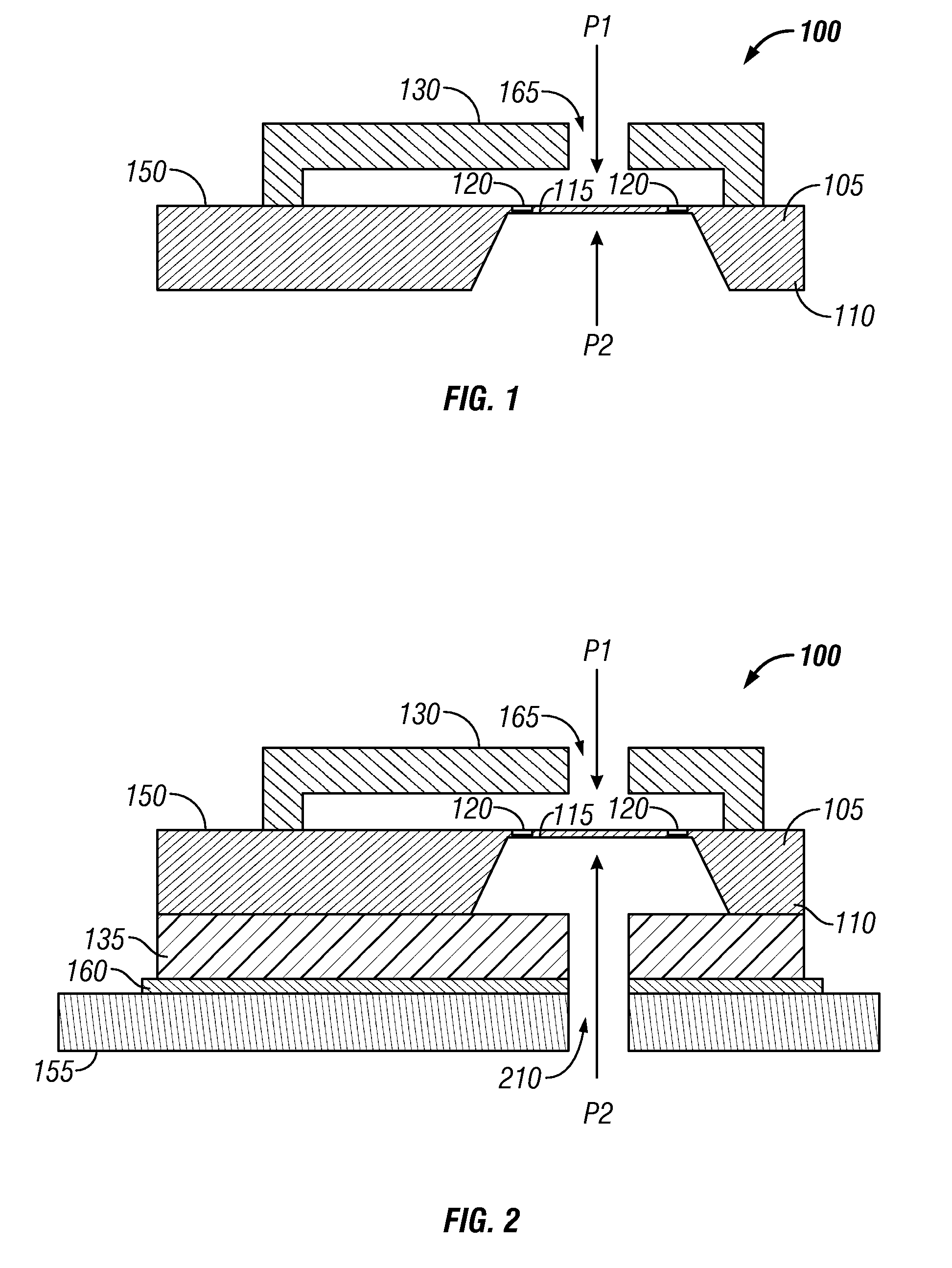
[0020]A MEMS-configured pressure sensor design utilizing wafer fabrication processes and microelectronic packaging techniques is disclosed herein. In such a device, a differential pressure sensor with high isolation between the sensed media and the sensor's electronics can be implemented. Referring to FIG. 1, a cross sectional view of a differential pressure sensor 100 is illustrated, in accordance with a preferred embodiment. Note that in FIGS. 1-4, identical or analogous parts or elements are generally indicated by identical reference numerals. The pressure sensor 100 generally includes a MEMS-configured pressure sense die 150 with a top side 105 and a back side 110. The MEMS-configured pressure sense die 150 can be fabricated utilizing silicon piezoresistive technology or ca...


PUM


Abstract

Method and system for a wet / wet differential pressure sensor based on microelectronic packaging process. A top cap with a hole can be attached to a topside of a MEMS-configured pressure sense die with a pressure sensing diaphragm in order to allow sensed media to come in contact with the topside of the pressure sensing diaphragm. An optional constraint with a hole for stress relief can be attached to a backside of the pressure sense die. Adhesive and / or elastomeric seals and / or solder can be utilized to seal the pressure sense die allowing sensed media to come in contact with both sides of the pressure sensing diaphragm without coming into contact with wirebonds and other metallized surfaces. The MEMS-configured pressure sense die can also be bonded to a substrate with standard die attach materials. Such microelectronic packaging processes yield a high performance and cost effective solution thereby providing wet-wet pressure sensing capability.

Description

TECHNICAL FIELD[0001]Embodiments are generally related to sensor methods and systems. Embodiments are also related to differential pressure sensor for use in wet / wet applications. Embodiments are also related to differential pressure sensor designs based on microelectronic and / or MEMS (Micro electromechanical System) packaging processes.BACKGROUND OF THE INVENTION[0002]Pressure sensors or pressure transducers can be utilized in a wide range of sensing applications. In many cases, it is desirable to measure the pressure of a particular type of media (e.g., usually gases or liquids) such as water, fuel, oil, acids, bases, solvents and corrosive gases. The sensed media can also include (but need not be limited to) air, nitrogen, industrial process gases, water, automotive fluids, pneumatic fluids, coolants, industrial chemicals, etc. For such applications, pressure sensors can be utilized to accurately sense the pressure of the media.[0003]In particular, one type or configuration of pr...

Claims


Application Information

Patent Timeline
Patent Type & Authority Applications(United States)
IPC IPC(8): G01F1/38
CPCG01L13/025G01L9/0054G01L19/145G01L19/0069G01L19/147G01L19/148H01L2224/48091H01L2224/48247H01L2224/73265H01L2924/10155H01L2924/15151H01L2924/16151H01L2924/16235H01L2924/00014
Inventor ROZGO, PAULBRADLEY, ALISTAIRJONES, RYAN S.RICKS, LAMAR F.
Owner HONEYWELL INT INC
Why Eureka
Try Eureka