Unlock instant, AI-driven research and patent intelligence for your innovation.

Disk brake with an improved structure

Active Publication Date: 2010-05-20
SUZHOU TORIN DRIVE EQUIP
View PDF2 Cites 6 Cited by
  • Summary
  • Abstract
  • Description
  • Claims
  • Application Information

AI Technical Summary

Benefits of technology

[0014]An aspect of an embodiment of the present invention is directed toward a disk brake with an improved structure, which can adjust automatically in any state, and ensure even clearance at the sides of the brake disk in the middle point between the friction plates when the brake is in charged state, and thereby enhances safety of the braking system and brings maintenance and service convenience.
[0023]Since embodiments of the present invention employ the aforementioned structure, the embodiments of the present invention provide the following enhancements: 1. By omitting, the small spring and adjusting screw in the prior art, the problem of adjusting screw colliding with the mounting plane of the mounting base frequently under the action of the small spring and thereby getting loose can be avoided; 2. A problem in the prior art of the brake disk having to be readjusted due to the displacement as a result of the bending deflection of the main shaft after the load is attached to the main shaft, is solved; instead, in embodiments of the present invention, the brake can adjust automatically in any state; when the brake is in charged state, the clearance formed at the middle position between the two friction plates at the each side of the brake disk is even clearance; therefore, the brake disk will not chafe either friction plate and produce noise; as the result, the life-span of the brake is increased, and the safety of the braking system is enhanced; 3. No readjustment is required in any case once the brake is installed and adjusted; therefore, the maintenance and service labor is minimized.

Problems solved by technology

However, the small working clearance A causes some drawbacks as well: when the elevator cabin is hung onto the traction wheel (18) on the traction machine, the traction wheel (18) bears radial force F, which also acts on the main shaft (17) and thereby causes some bending deflection on the main shaft (17); as a result, the brake disk (1) results in inclination, and therefore the acting point of the disk brake has some displacement and inclination, following the inclination of the brake disk (1).
Moreover, commercial traction machines with disk brakes available in the market usually have to be debugged on site after the elevator cabin is hung onto the traction machine; however, the adjustment of the aforementioned clearance must be done by a professional technician; such adjustment work adds a big expense in the installation on after-sale service of products.
Furthermore, the axial displacement of the brake disk (1) will vary with the load in the elevator cabin, and therefore the brake cannot be tuned up to the normal state.
In addition, in a specific embodiment of that invention, one tongue piece of the rocker rod is fixed to the circumferential surface of the moving plate, while the other tongue piece is fixed to the upper part of the brake calipers; however, in such a caliper type brake, the clearance cannot be halved accurately between the two sides of the brake disk, due to the irrational fixing points of the rocker rod structure and uneven stress.
Furthermore, when the bending deflection reaches to a certain degree, the clearance even cannot be allocated correctly.

Method used


Image

  • Disk brake with an improved structure
  • Disk brake with an improved structure
  • Disk brake with an improved structure

Examples


embodiment 1

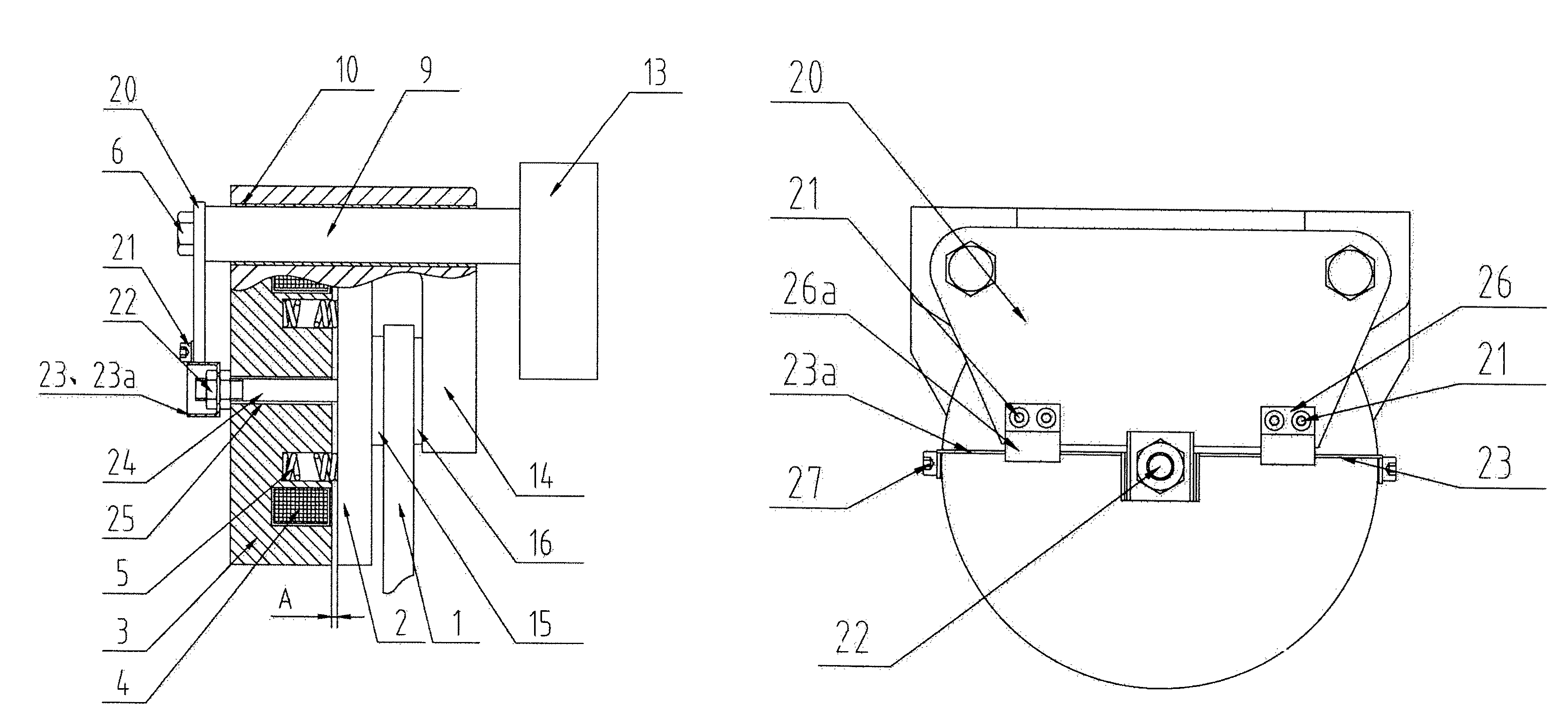
[0034]Please refer to FIG. 4, FIG. 5, and in combination with FIG. 6, FIG. 7. As shown in the Figures, the disk brake comprises a brake disk (1), a moving disk (2), a fixed disk (3), a brake coil (4), a brake spring (5), left and right friction plates (15, 16), a bolt (6), a guide rod (9), a sleeve (10), a mounting base (13), a brake caliper (14), a fixed rod (24), a first lever and a second lever (23, 23a), a first spring clamp and a second spring clamp (26, 26a), and a fixed plate (20), wherein, the moving disk (2) and fixed disk (3) are in disk shape, the brake coil (4) and brake spring (5) are arranged in the fixed disk (3), the brake calipers (14) and the fixed disk (3) are fixed together with screws; the left friction plate (15) is adhered to the inner side of the moving disk (2), the right friction plate (16) is adhered to the inner side of the brake calipers (14), and the left and right friction plates (15, 16) are used to clamp the brake disk (1); a mounting hole is opened ...

embodiment 2

[0035]Compared to the embodiment 1, the difference of this embodiment lies in: the fixed rod (24) comprises two rods, the fixed plate (20) comprises two plates, and the first and second levers (23, 23a) are two parts fabricated separately. Specifically, one end of the two fixed rods (24) is fixed to the disk plane of the moving disk (2) respectively, and the other end of the two fixed rods (24) passes through the fixed disk (3) and is fixed to one end of the first and second levers (23, 23a) that are fabricated into separate parts, respectively; the two fixed plates (20) are fixed to the extension end of the mounting base (13) with fasteners, and one end of the first / second spring clamp (26, 26a) is connected to the corresponding fixed plate (20) respectively with fasteners. The other elements of this embodiment is identical to that of the embodiment 1.

Example of Application:

[0036]When the brake is in a braking state, the bending deflection of the main shaft varies with the load, an...


PUM


Abstract

A disk brake comprising: a brake disk, a moving disk, a fixed disk, a mounting base, a guide rod, a fixed rod, first and second levers, a fixed plate, and first and second spring clamps. Here, one end of the fixed rod is fixed to a plane of the moving disk, the other end of the fixed rod passes through the fixed disk and is fixed to one end of the first / second lever, and the other end of the first / second lever is fixed to the circumferential surface of the fixed disk on the center line of the fixed disk; the fixed plate is fixed to either the guide rod or the mounting base; one end of the first / second spring clamp is connected to the fixed plate, and the other end of the first / second spring clamp is clamped at the middle position between the first and second levers.

Description

CROSS-REFERENCE TO RELATED APPLICATION[0001]This application claims priority to and the benefit of Chinese Patent Application No. 200810235986.5, filed in the Chinese Intellectual Property Office on Nov. 19, 2008, the entire contents of which are incorporated herein by reference.FIELD OF THE INVENTION[0002]The following description relates to a magnetic brake, in particular to a disk brake for an elevator traction machine, and an improved structure for the disk brake.BACKGROUND OF THE INVENTION[0003]In the prior art, a disk brake can be applied on a traction machine of an elevator, with its structure shown in FIG. 1 and FIG. 2. It comprises a brake disk (1), a moving disk (2), a fixed disk (3), left and right friction plates (15, 16), a brake coil (4), a brake spring (5), a bolt (6), a spring bulkhead (7), a small spring (8), a guide rod (9), a sleeve (10), a first locknut (11), an adjusting bolt (12), a mounting base (13), and a brake calipers (14); wherein, the brake coil (4) and ...

Claims


Application Information

Patent Timeline
IPC IPC(8): F16D55/02
CPCB66D5/30B66D5/14
Inventor CAO, JIANWENZHANG, HEFANG, WENNAQU, YESHENGZHOU, WEI
Owner SUZHOU TORIN DRIVE EQUIP