
Method for stretching carbon nanotube film

a carbon nanotube and film technology, applied in the field of nanomaterial films and methods for stretching the same, can solve the problems of limiting the application of carbon nanotubes, the width of carbon nanotube film and carbon nanotube yarn is restricted, and the size of carbon nanotube arrays is limited to about 4 inches

Active Publication Date: 2010-05-20
TSINGHUA UNIV +1
View PDF21 Cites 19 Cited by
  • Summary
  • Abstract
  • Description
  • Claims
  • Application Information

AI Technical Summary

Benefits of technology

[0007]Carbon nanotube yarn is one important macro-scale carbon nanotube structure. Examples of a method for making a carbon nanotube yarn is taught by U.S. Pat. No. 7,045,108 to Jiang et al. The carbon nanotube yarn is directly drawn from a super-aligned carbon nanotube array. The carbon nanotube yarn includes a plurality of carbon nanotubes joined end-to-end by van der Waals attractive forces therebetween. Specifically, the carbon nanotube yarn includes a plurality of successively oriented carbon nanotube segments joined end-to-end by van der Waals attractive force therebetween. Each carbon nanotube segment includes a plurality of carbon nanotubes parallel to each other, and combined by van der Waals attractive force therebetween. The length of the carbon nanotube yarn can vary. However, the width of the carbon nanotube yarn is related to a size of the carbon nanotube array.

Problems solved by technology

The particle or powder-shaped carbon nanotubes limit the applications the carbon nanotubes can be used.
However, both the width of the carbon nanotube film and the carbon nanotube yarn are restricted by a size of the carbon nanotube array.
Nowadays, the size of carbon nanotube arrays is limited to about 4 inches, which is not conducive to preparing carbon nanotube films with large area.

Method used


Image

  • Method for stretching carbon nanotube film
  • Method for stretching carbon nanotube film
  • Method for stretching carbon nanotube film

Examples


Embodiment Construction

[0019]References will now be made to the drawings to describe, in detail, embodiments of the present carbon nanotube film and method for stretching the same.

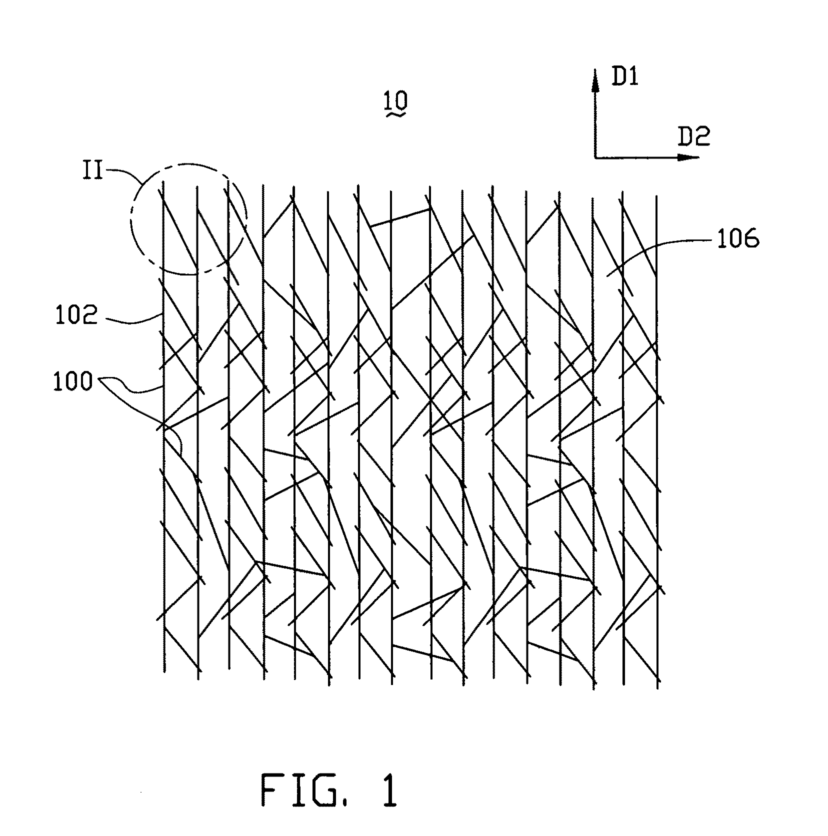
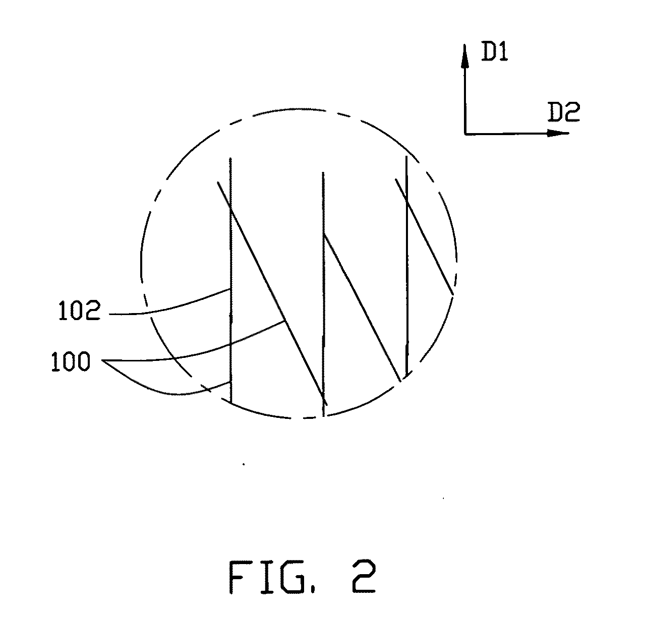
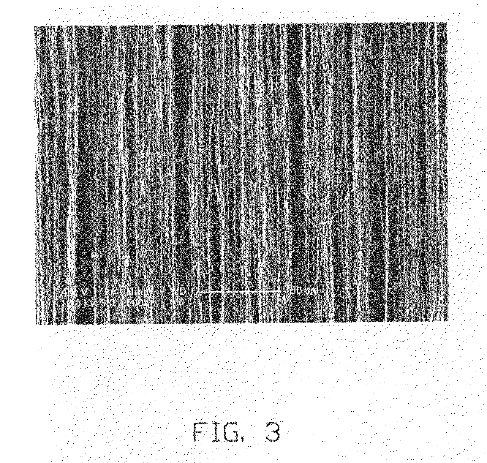
[0020]Referring to FIG. 1 through FIG. 4, one embodiment of a carbon nanotube film 10 includes a plurality of carbon nanotubes 100. A part of the carbon nanotubes 100 are joined end to end to form a plurality of carbon nanotube strings 102. Each carbon nanotube string 102 includes a plurality of carbon nanotubes 100 joined end to end. The carbon nanotubes 100 in the carbon nanotube string 102 are substantially aligned along an axis of the carbon nanotube string 102, and attracted by van der Waals attractive force therebetween. The carbon nanotube film 10 can include a plurality of carbon nanotube strings 102 located side by side. The carbon nanotube strings 102 are attracted by van der Waals attractive force therebetween. The carbon nanotube strings 102 can be separated from each other. The carbon nanotube strings 102 are unifor...


PUM

PropertyMeasurementUnit
Fractionaaaaaaaaaa
Fractionaaaaaaaaaa
Fractionaaaaaaaaaa

Abstract

A method for stretching a carbon nanotube film includes providing one or more carbon nanotube films and one or more elastic supporters, attaching at least one portion of the one or more carbon nanotube films to the one or more elastic supporters, and stretching the elastic supporters.

Description

RELATED APPLICATIONS[0001]This application is related to copending applications entitled, “CARBON NANOTUBE FILM”, filed ______ (Atty. Docket No. US23877); and “CARBON NANOTUBE FILM”, filed ______ (Atty. Docket No. US24829). Disclosures of the above-identified applications are incorporated herein by reference.BACKGROUND[0002]1. Technical Field[0003]The present disclosure relates to nanomaterial films and methods for stretching the same and, particularly, to a carbon nanotube film and a method for stretching the same.[0004]2. Discussion of Related Art[0005]Carbon nanotubes have received a great deal of interest since the early 1990s. Carbon nanotubes have interesting and potentially useful electrical and mechanical properties. Due to these and other properties, carbon nanotubes have become a significant focus of research and development for use in electron emitting devices, sensors, and transistors.[0006]Generally, carbon nanotubes prepared by conventional methods are in particle or p...

Claims


Application Information

Patent Timeline
IPC IPC(8): B29C55/00
CPCB29C55/04D02J1/22B29K2105/162
Inventor JIANG, KAI-LIFENG, CHENXIAO, LINCHEN, ZHUOLIU, LIANGFAN, SHOU-SHANLI, QUN-QINGQIAN, LILIU, KAIWEI, YANG
Owner TSINGHUA UNIV
Learn More