Level-shift circuit

a level-shift circuit and circuit technology, applied in logic circuits, logic circuit coupling arrangements, pulse techniques, etc., can solve problems such as unreliable signal transmission to the high-side switch, and achieve the effect of preventing unreliable signal transmission and reliable signal transmission

Inactive Publication Date: 2010-05-20
SANKEN ELECTRIC CO LTD
View PDF1 Cites 16 Cited by
  • Summary
  • Abstract
  • Description
  • Claims
  • Application Information

AI Technical Summary

Benefits of technology

[0017]Namely, by detecting the middle point potential, the high-side switch and the low-side switch can be driven at a proper time, and a short circuit current due to a recovery current of each switching element occurring at a time when a drive signal is output during fluctuation of the middle point potential can be prevented from flowing in the half-bridge circuit or the full-bridge circuit. Therefore, the present invention can prevent unreliable signal transmission which occurs by undesired capacitor charging or discharging due to external factor such as voltage fluctuation of the different potential level, which realizes that reliable signal transmission is carried out.
[0018]Further, when an electric current is detected by the electric current detection circuit, the mask circuit masks a drive signal to be input into the set level circuit and the reset level circuit during the period when the electric current flows into or from the first capacitor and / or the second capacitor. This also can prevent unreliable signal transmission which occurs by undesired capacitor charging or discharging due to external factor such as voltage fluctuation of the different potential level, which realizes that reliable signal transmission is carried out.

Problems solved by technology

This brings the latch circuit to malfunction, which causes unreliable signal transmission to the high-side switch.

Method used


Image

  • Level-shift circuit
  • Level-shift circuit
  • Level-shift circuit

Examples


first exemplary embodiment

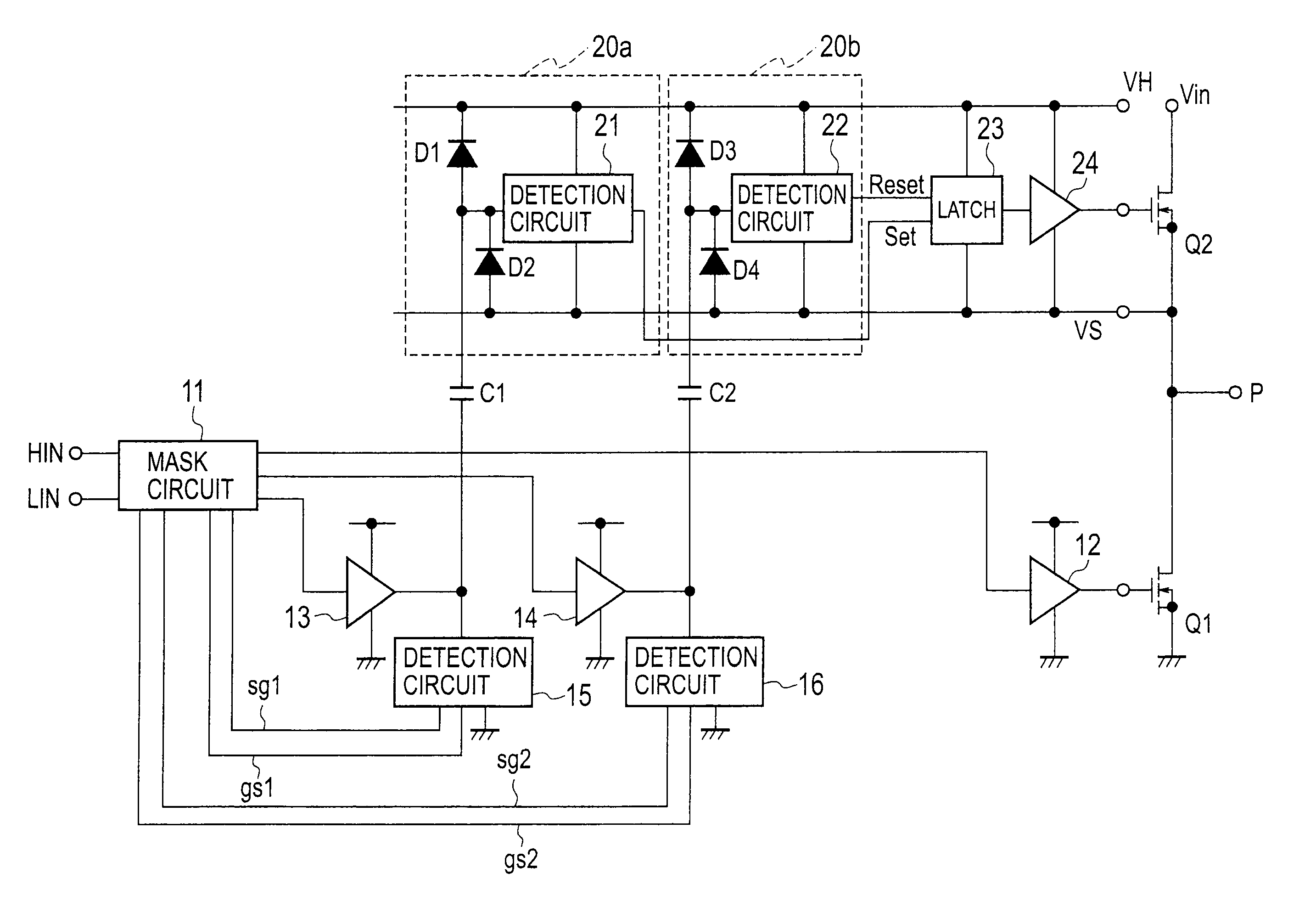
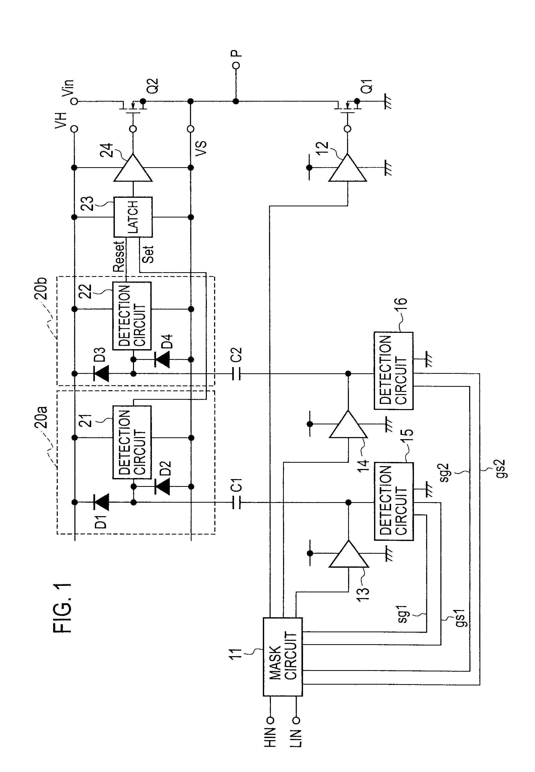
[0027]FIG. 1 is a block diagram illustrating a level-shift circuit according to a first exemplary embodiment of the present invention. In the level-shift circuit, a series circuit is connected between a power source Vin and the ground. In the series circuit, a low-side switch Q1 composed of MOSFET is connected to a high-side switch Q2 composed of MOSFET in series. The low-side switch Q1 and the high-side switch Q2 make up a half-bridge circuit.

[0028]It is noted that instead of the half-bridge circuit, a full-bridge circuit may be employed.

[0029]A mask circuit 11 outputs to a drive circuit 12 a low-side instruction signal input into a LIN terminal thereof. The drive circuit 12 drives the low-side switch Q1 based on the low-side instruction signal from the mask circuit 11.

[0030]The mask circuit 11 outputs to buffers 13 and 14 a high-side instruction signal input into a HIN terminal thereof. A first capacitor C1 is connected to an output of the buffer 13. The buffer 13 sends a set sign...

second exemplary embodiment

[0078]FIG. 6 is a block diagram illustrating a level-shift circuit according to a second exemplary embodiment of the present invention. The level-shift circuit shown in FIG. 6 differs from the level-shift circuit shown in FIG. 1 in that a detection circuit 17, a third capacitor C3, diodes D5 and D6 and a buffer 18 are added and a signal detection method of detection circuits 21a and 22a in the detection circuits 15a and 16a is changed in a differential manner.

[0079]A series circuit composed of the diodes D5 and D6 is connected between the high potential VH and the high-side ground potential VS. A connection point of the diodes D5 and D6 is connected to the detection circuit 21a of a first high-side signal detection circuit 20c and the detection circuit 22a of a second high-side signal detection circuit 20d and connected to the detection circuit 17 and the buffer 18 via the third capacitor C3.

[0080]The detection circuit 17 detects a charging current flowing into the third capacitor C...


PUM


Abstract

A level-shift circuit converts a first voltage level into a second voltage level different from the first voltage level. The level-shift circuit includes a first high-side signal detection circuit, a second high-side signal detection circuit, a drive circuit and electric current detection circuits. The first high-side signal detection circuit sets a logical voltage state of the second voltage level via a first capacitor. The second high-side signal detection circuit resets the logical voltage state of the second voltage level via a second capacitor. The drive circuit on-off drives a high-side switch connected to a low-side switch in series by a set signal of the first high-side signal detection circuit and a reset signal of the second high-side signal detection circuit. The electric current detection circuits detect an electric current flowing into or from the first and/or second capacitors.

Description

CROSS REFERENCE TO RELATED APPLICATION[0001]This application claims benefit of priority under 35 U.S.C. §119 to Japanese Patent Application No. 2008-293413, filed on Nov. 17, 2008, the entire contents of which are incorporated by reference herein.BACKGROUND OF THE INVENTION[0002]1. Field of the Invention[0003]The present invention relates to a level-shift circuit that carries out a level-shift needed for a switch in a half-bridge configuration.[0004]2. Description of the Related Art[0005]As a conventional level-shift circuit, for example, there has been known a level-shift circuit disclosed in a patent document 1 (Published Japanese Translation of PCT International Application No. 2005-512444).[0006]In this level-shift circuit, for a high-side ground potential at a middle point between a high-side switch and a low-side switch in a half-bridge configuration, a voltage level greatly varies within a certain range (e.g., a range of 0 V to 400 V with respect to the ground potential), in ...

Claims


Application Information

Patent Timeline
Patent Type & Authority Applications(United States)
IPC IPC(8): H03K19/0175
CPCH03K17/16H03K2217/0081H03K19/017545H03K17/6871
Inventor OSAKA, SHOHEI
Owner SANKEN ELECTRIC CO LTD
Why Eureka
Try Eureka