Antenna device and radar apparatus

a radar and antenna technology, applied in the direction of antennas, instruments, antenna details, etc., can solve the problems of asymmetrical phase difference of signal beams, large aperture area of array antennas, and degraded measurement accuracy of target angle in monopulse radar systems

Inactive Publication Date: 2010-05-20
KK TOSHIBA
View PDF13 Cites 13 Cited by
  • Summary
  • Abstract
  • Description
  • Claims
  • Application Information

AI Technical Summary

Benefits of technology

[0015]the interval of the subarray antenna...

Problems solved by technology

As a result, an aperture area of the array antenna gets large.
However, the array antenna with the asymmetrical inter-digital structure for a scan plane causes an asymmetrical phase difference of a signal bea...

Method used


Image

  • Antenna device and radar apparatus
  • Antenna device and radar apparatus
  • Antenna device and radar apparatus

Examples


modified example 1

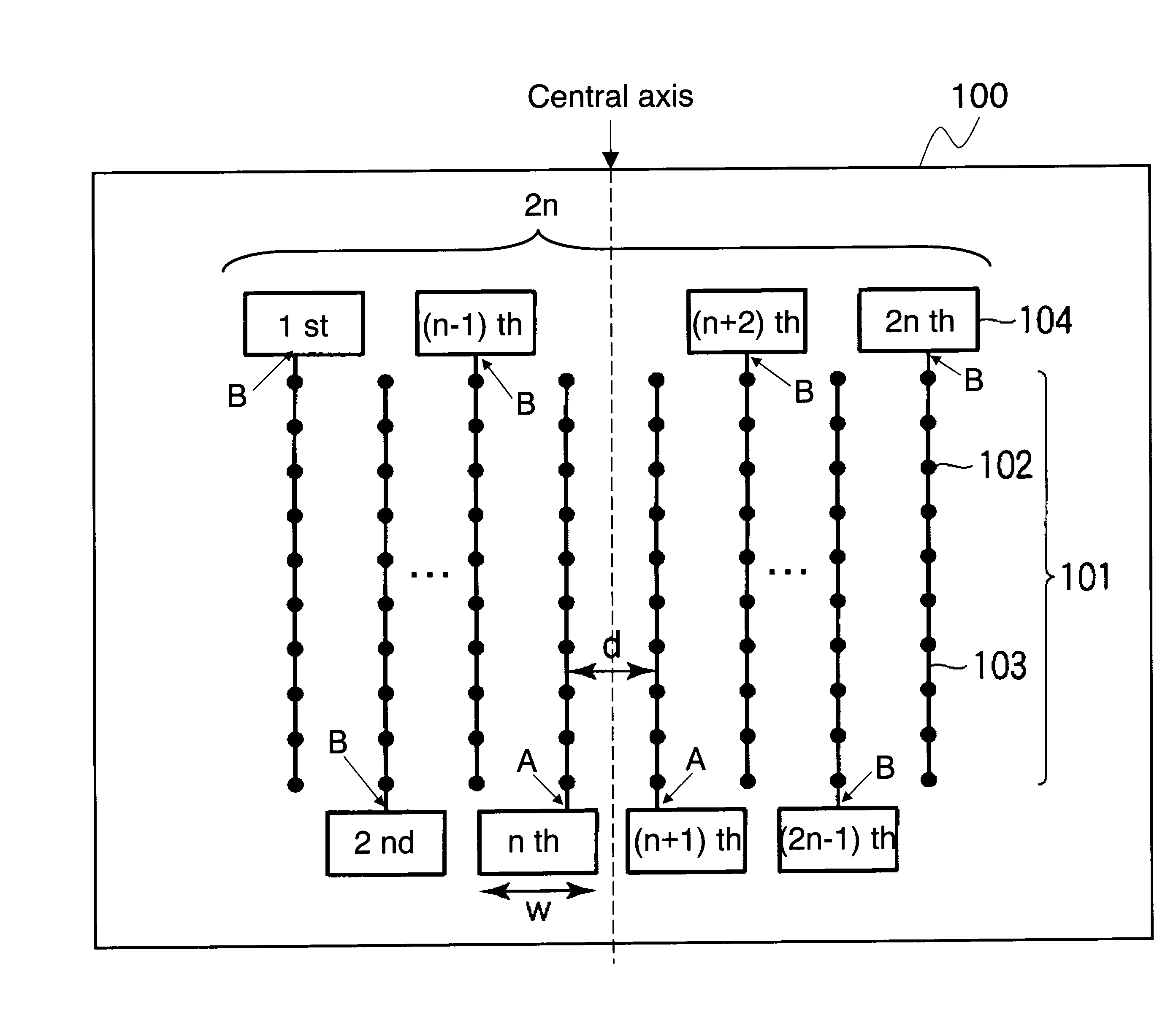
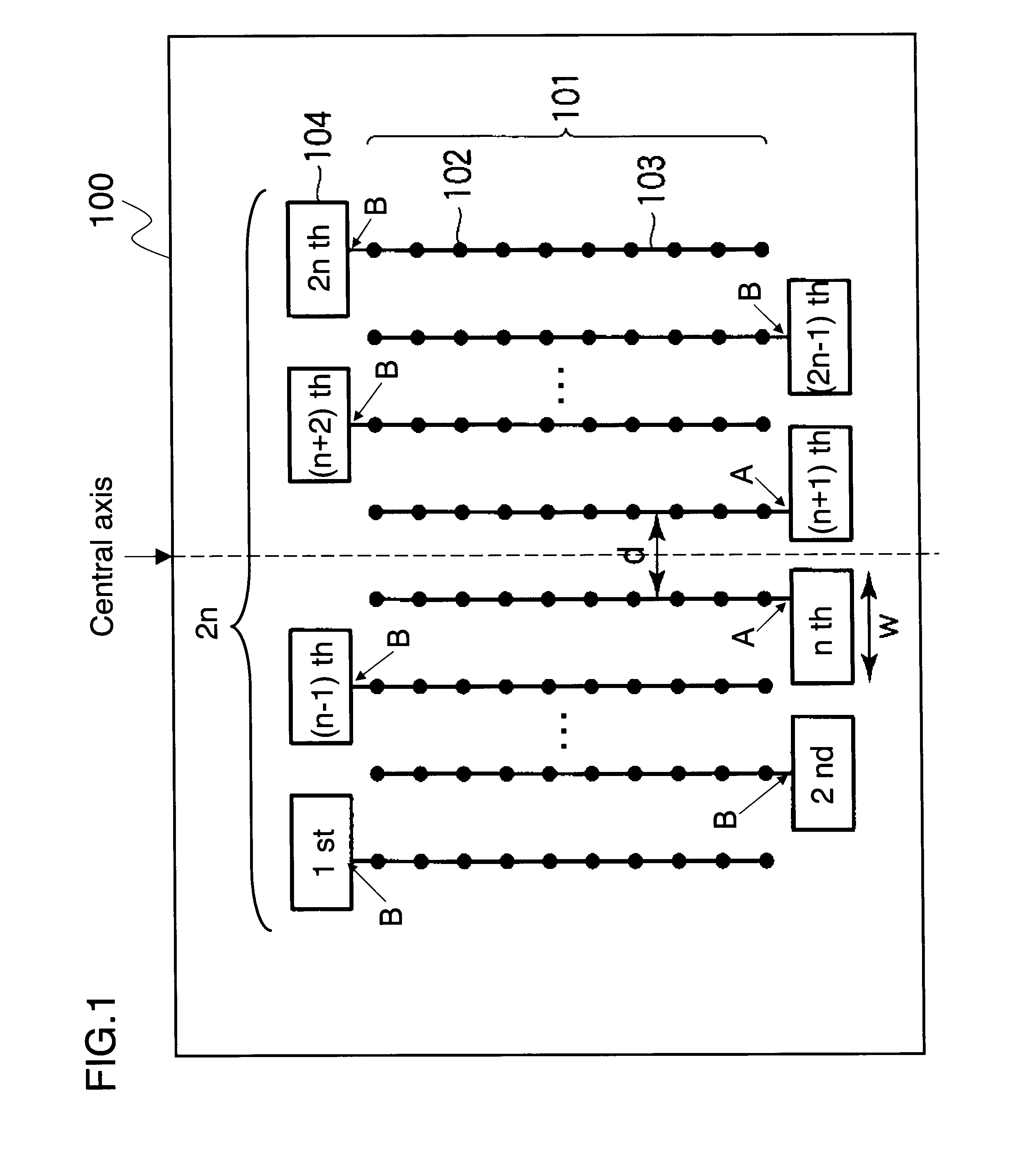
[0045]Hereinafter, a modified example of an antenna device 100′ will be described. FIG. 5 shows the antenna device 100′ which the number of the subarray antennas is even.

[0046]The antenna device 100′ includes the subarray antennas 101 and the feeding interfaces 104 as same as the antenna device 100. While the n th and (n+1) th feeding interfaces 104, which are the closest to the central axis, are shifted away from each other to avoid giving interference in the antenna device 100 of FIG. 1, they are located at both outside of the 1st and 2n th subarray antennas in the antenna device 100′ of FIG. 5. The n th and (n+1) th feeding lines 103 are extended longer than other feeding lines 103. In the antenna device 101′, the n th and (n+1) th feeding lines 103 have bend structures to connect to the n th and (n+1) th feeding interfaces 104, respectively.

[0047]FIG. 6 shows a prototype 600 of the antenna device 100′. The prototype 600 is same as the prototype 400, except that the feeding lines...

modified example 2

[0050]Hereinafter, another modified example will be described. In the modified example 2, the subarray antenna 101 is any one of a waveguide slotted subarray antenna, a conductive waveguide slotted subarray antenna, a patch antenna with the triplate line, a patch antenna with the microstrip line, and a horn array antenna. In the modified example 2, we will describe variation of alignments of the antenna elements 102.

[0051]FIGS. 7-9 show subarray antennas 701-901 which have different alignments of the antenna elements 102. As shown in FIG. 7, each antenna element 102 may be located at an end of a sub feeding line 705 which is branched to one side from the feeding line 103. As shown in FIG. 8, each antenna element 102 may be located at the end of a sub feeding line 805 which is branched to both sides from the feeding line 103. Moreover, as shown in FIG. 9, the antenna elements 102 may be located at the end of a sub feeding line 905 branching T-shaped three times from the feeding lines...


PUM


Abstract

An antenna device includes subarray antennas including antenna elements and feeding interfaces. Each feeding interface is connected to each of subarray antennas. The subarray antennas are arranged parallel to each other with an interval on a plane to be symmetrical about a central axis. The interval is less or equal than a free-space wavelength. The central axis is along with the center of two adjacent subarray antennas arranged at middle of the subarray antennas when the number of the subarray antennas is even. Moreover, the central axis is along with one subarray antenna arranged at the middle of the subarray antennas when the number of the subarray antennas is odd.

Description

CROSS REFERENCE TO RELATED APPLICATIONS[0001]This application is based upon and claims the benefit of priority from the Japanese Patent Application No. 2008-292492, filed on Nov. 14, 2008, the entire contents of which are incorporated herein by reference.BACKGROUND OF THE INVENTION[0002]1. Field of the Invention[0003]The present invention relates to an antenna device and a radar apparatus.[0004]2. Description of the Related Art[0005]In monopulse radar systems, an array antenna forms a beam to transmit a signal. Then, the array antenna receives an echo signal which is corresponded to the signal in order to measure a target angle.[0006]The array antenna includes several subarray antennas as disclosed in “Antenna Engineering Handbook”, Ohmsha, pp. 339-pp. 445. One side of each subarray antenna is connected to a feeding interface such as a waveguide or a line such as a triplate line and a microstrip line in order to feed a signal. These feeding methods are disclosed by H. Iizuka, K. Sak...

Claims


Application Information

Patent Timeline
IPC IPC(8): G01S13/00H01Q21/00
CPCH01Q21/061H01Q1/3233
Inventor SHIJO, TETSUITO, TAKAYOSHIOBAYASHI, SHUICHI
Owner KK TOSHIBA
Why Eureka
Try Eureka