Softbox

a softbox and light technology, applied in the field of softboxes, can solve the problems of unsatisfactory light emission from such softboxes, insufficient illumination effect attainable with conventional control grids, and insufficient attachment of known softboxes to spotlight sources, so as to simplify the mounting and avoid undesired lighting of the object surroundings

Active Publication Date: 2010-05-20
KARLE STEFAN
View PDF5 Cites 33 Cited by
  • Summary
  • Abstract
  • Description
  • Claims
  • Application Information

AI Technical Summary

Benefits of technology

[0009]Said softbox facilitates both its assembly and the orientation of illumination in that the supporting structure can be mounted, in a position of non-use, in that the tension rods of the softbox are simply inserted into a corresponding receiving means provided in the attachment device and, by spreading the same, arrested in a use configuration. Moreover, an undesired illumination of the object surrounding is eliminated.
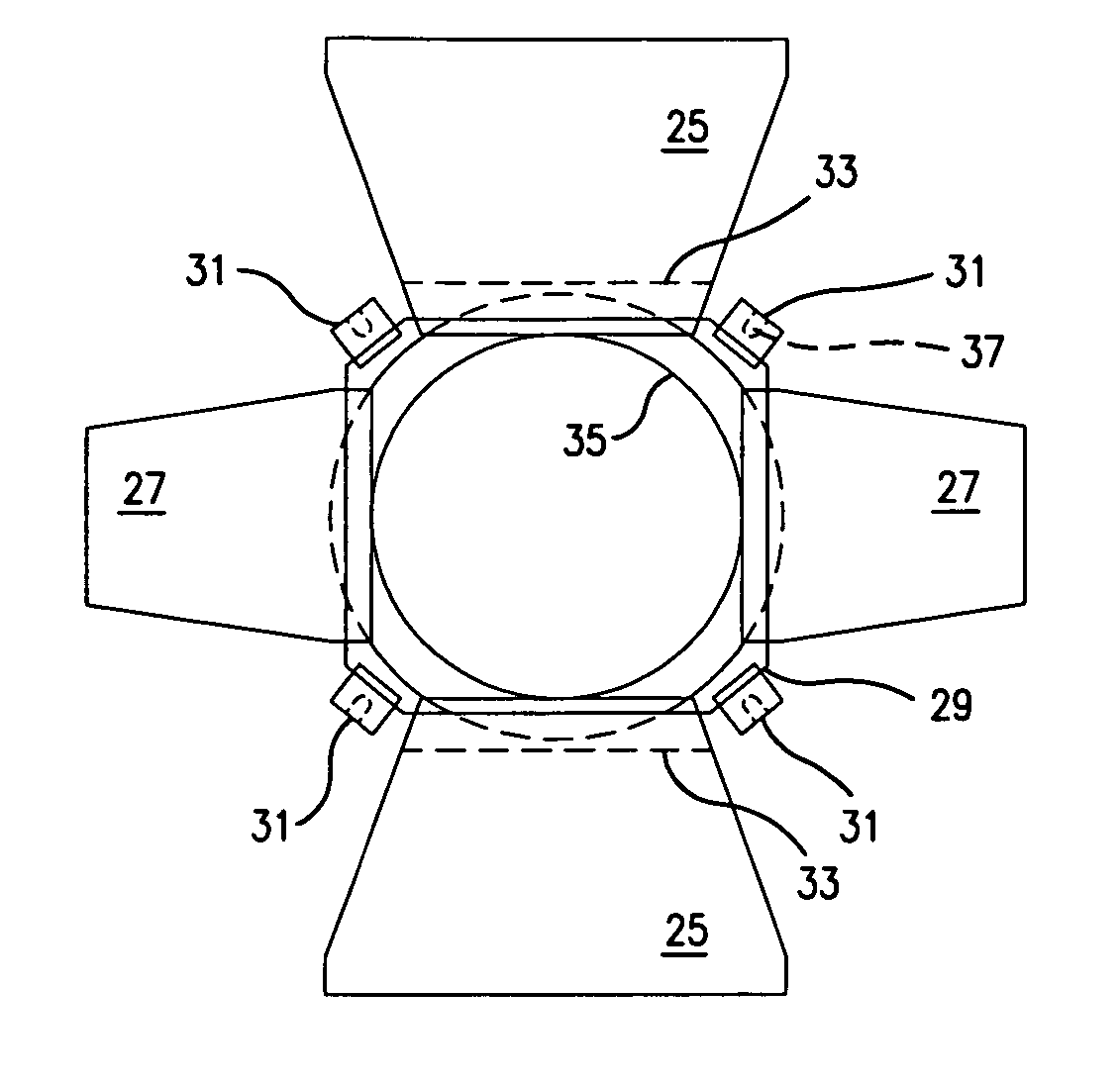
[0011]According to an embodiment, the supporting structure comprises plural components which are positioned between, and alternate with, the hinges of the barn doors. According to further embodiments, the components are provided to be pivotal about pivot axles or also arrestable in a use configuration. According to a preferred embodiment, the pivot axles of the attachment components and the pivot axles of the barn doors form part of the same wire which encloses the light emission aperture of the spotlight source. To this end, the wire is preferably of generally octagonal shape having four longer sides of mutually the same length and four shorter sides of again mutually the same length extending alternately in circumferential direction. In other embodiments, there are two like wires on opposite sides of the light emitting aperture, each wire having doubly bent ends, wherein the first bend forms an about 140° angle and the outer bend forms an about 50° angle to the other side. Thus, the middle portion of each wire can serve as an axis for one barn door, while the end portions of each wire can serve as axes for the adjacent barn doors. The components and pivot axles are preferably attached to a mounting ring which, in turn, is rotatably fixed to the spotlight source by means of three or four retainers. One of the retainers may be provided to be folded out in order to enable a lateral removal of the mounting ring if neither the barn doors nor the softbox are to be used. In embodiments, the attachment components include holes for receiving poles of softboxes with varying sizes, wherein the holes having different size also may be arranged at different angles to the light beam axis. The smaller sized holes may be formed inside the larger diameter ones, but somewhat deeper, to accommodate either kind of poles. For ease of handling, there may be provided a rotatable guiding member for the poles.
[0016]For blocking undesired light beams having a large angle with respect to the normal of a large light exit plane, the control grid is in some embodiments surrounded by a strip which has several elastic holding straps at its outer circumference. Rigid parts of tensioning components engage into these elastic holding straps, which rigid parts may be configured to be opened / closed for attachment to the holding straps. The rigid parts each have an elastic flexible part, e.g. a string made of a resilient material, which part is wound around a frame present and is then fixed to a clamp of the rigid part. With such an arrangement, the control grid may easily, quickly and securely be fixed to a frame having arbitrary cross section. Te rigid part may have recesses adapted for several common frame cross sections.
[0018]This softbox simplifies its mounting and also the light directing, insomuch the frame may be mounted by simply inserting the tensioning poles of the softbox into respective recesses of the attachment device in a non-use position, and stretched out into the use position followed by arresting in the stretched-out position. In addition, an undesired lighting of the object surroundings may be avoided.

Problems solved by technology

It is known that the light emission from such softboxes is unsatisfactory insofar as the entire object environment is also illuminated by the same.
Attachment of known softboxes to the spotlight source is not yet fully satisfactory and, moreover, the illumination effect attainable with conventional control grid is perceived to be still insufficient.
Such a sagging would affect the control effect exerted by the light grid.

Method used


Image

  • Softbox
  • Softbox
  • Softbox

Examples


Embodiment Construction

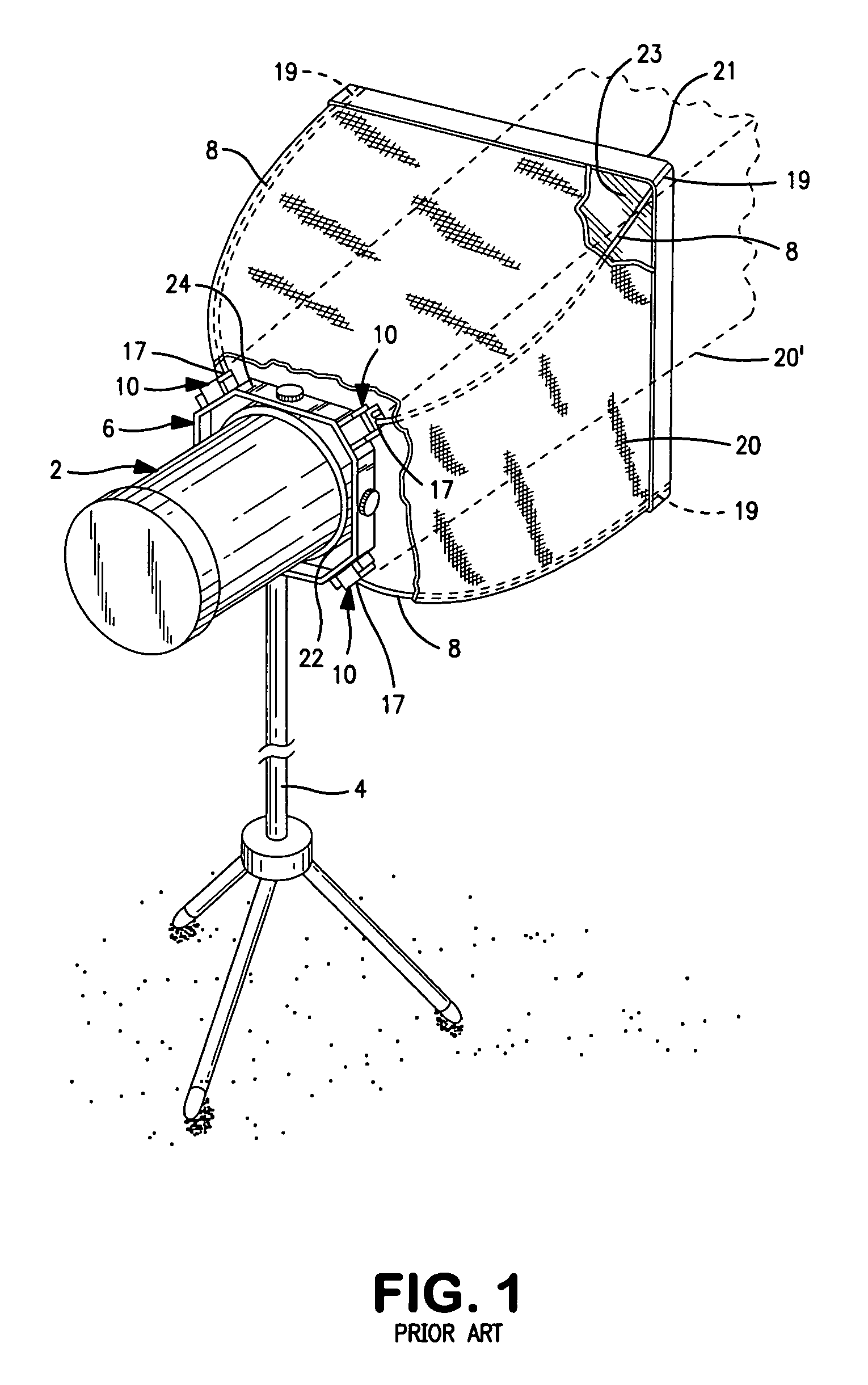
[0039]In a conventional softbox 20 illustrated in FIG. 1, four cloth-clad rods 8 which extend from the softbox are inserted into holes 17 of blocks 10 which, in turn, are fixed in position to a spotlight source 2 by means of a frame 6. The frame 6 is formed by a metal sheet strip 24 and fastened to a stand 4. The light emission aperture of the spotlight source 2 is enclosed by a mounting ring 22 to which the frame 6 is releasably attached. The light emission aperture 21 of the softbox comprises a translucent covering 23 and receiver 19 for accommodating the rods 8. The blocks 10 are tiltable, allowing the rods 8 to be collapsed (position 20′ of the softbox). If light gates, also referred to as barn doors, are to be used, the softbox 20, together with the attachment device, must first be disassembled from the frame 6 and blocks 10.

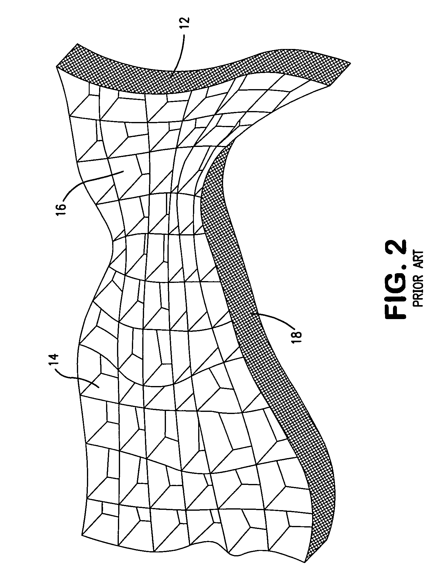
[0040]In the conventional control grid according to FIG. 2, differently slotted textile strips 14, 16 are inserted into each other crosswise. This array is...


PUM

PropertyMeasurementUnit
angleaaaaaaaaaa
angleaaaaaaaaaa
widthaaaaaaaaaa

Abstract

A softbox for a spotlight includes a device for mounting the softbox to the spotlight such that in operation, the spotlight shines through the softbox. For limiting the emerging angle of the light shining through the softbox, a light control grid is mounted at the light emitting aperture of the softbox. For mounting the light control grid to the light emitting aperture of the softbox, a frame surrounds the light emitting aperture of the softbox. The control grid for being mounted to the softbox is manufactured by fixing adjacent strips of a light absorbing material to one another.

Description

BACKGROUND OF THE INVENTION[0001]The present invention relates to a softbox for a spotlight source, comprising an attachment device and a light control grid, and to the latter devices as such.[0002]Light diffusion boxes, also known as softboxes, have long been used by photographers and camera crews to provide diffused lighting and to prevent hard shadows. Collapsible or otherwise disassemblable softboxes are especially useful for location shooting, because they are lightweight and transportable. Typically, they comprise a supporting structure of flexible rods over which a cloth is stretched. The inside surfaces of such softboxes may be coated with reflective material, as disclosed in German translation DE 698 09 374 T2 of European patent EP 0 917 668 B1. As compared to the actual spotlight source, such softboxes provide an enlarged light emission area so that each illuminated object point is struck by light beams from a larger solid angle range. Shadow borders thus blur to gradual b...

Claims


Application Information

Patent Timeline
Patent Type & Authority Applications(United States)
IPC IPC(8): F21V17/06B23P17/00
CPCF21V17/06Y10T29/49G03B15/02
Inventor KARLE, STEFAN
Owner KARLE STEFAN
Why Eureka
Try Eureka