Double-sided ball end mill cutting insert and tool therefor

a cutting insert and ball end mill technology, which is applied in the direction of shaping cutters, turning machine accessories, manufacturing tools, etc., can solve the problem of increasing the overall operating cost of such a conventional end mill

Active Publication Date: 2010-05-20
KENNAMETAL INC
View PDF33 Cites 43 Cited by
  • Summary
  • Abstract
  • Description
  • Claims
  • Application Information

AI Technical Summary

Problems solved by technology

As a result, one-half of the cutting insert is not being used, which

Method used


Image

  • Double-sided ball end mill cutting insert and tool therefor
  • Double-sided ball end mill cutting insert and tool therefor
  • Double-sided ball end mill cutting insert and tool therefor

Examples


Embodiment Construction

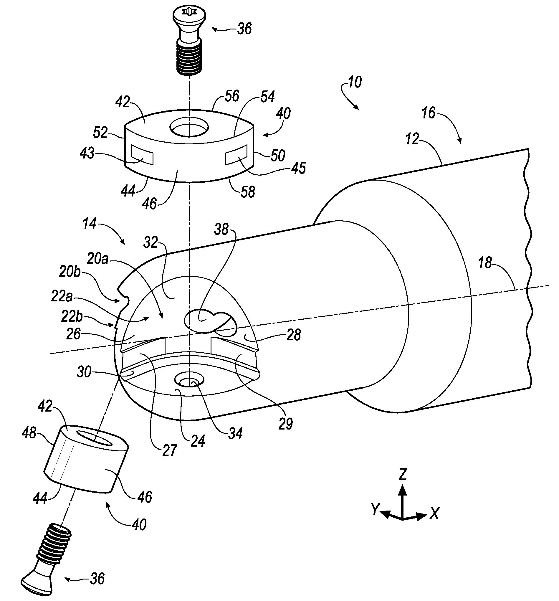
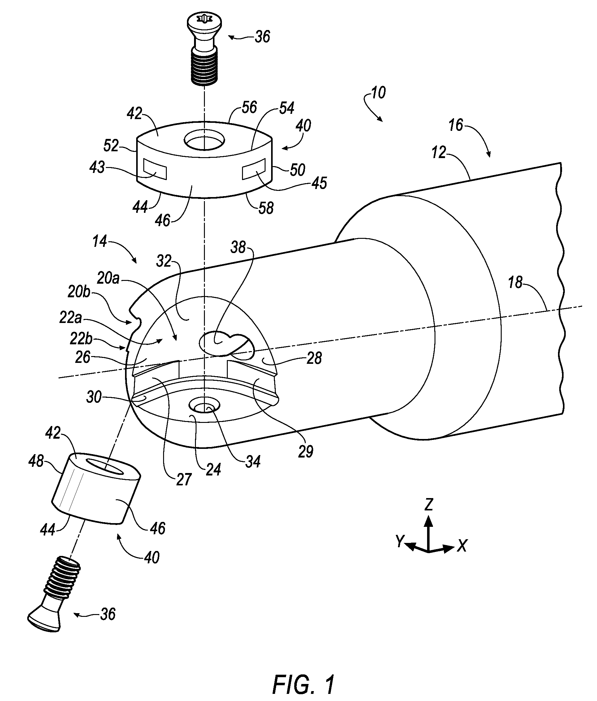
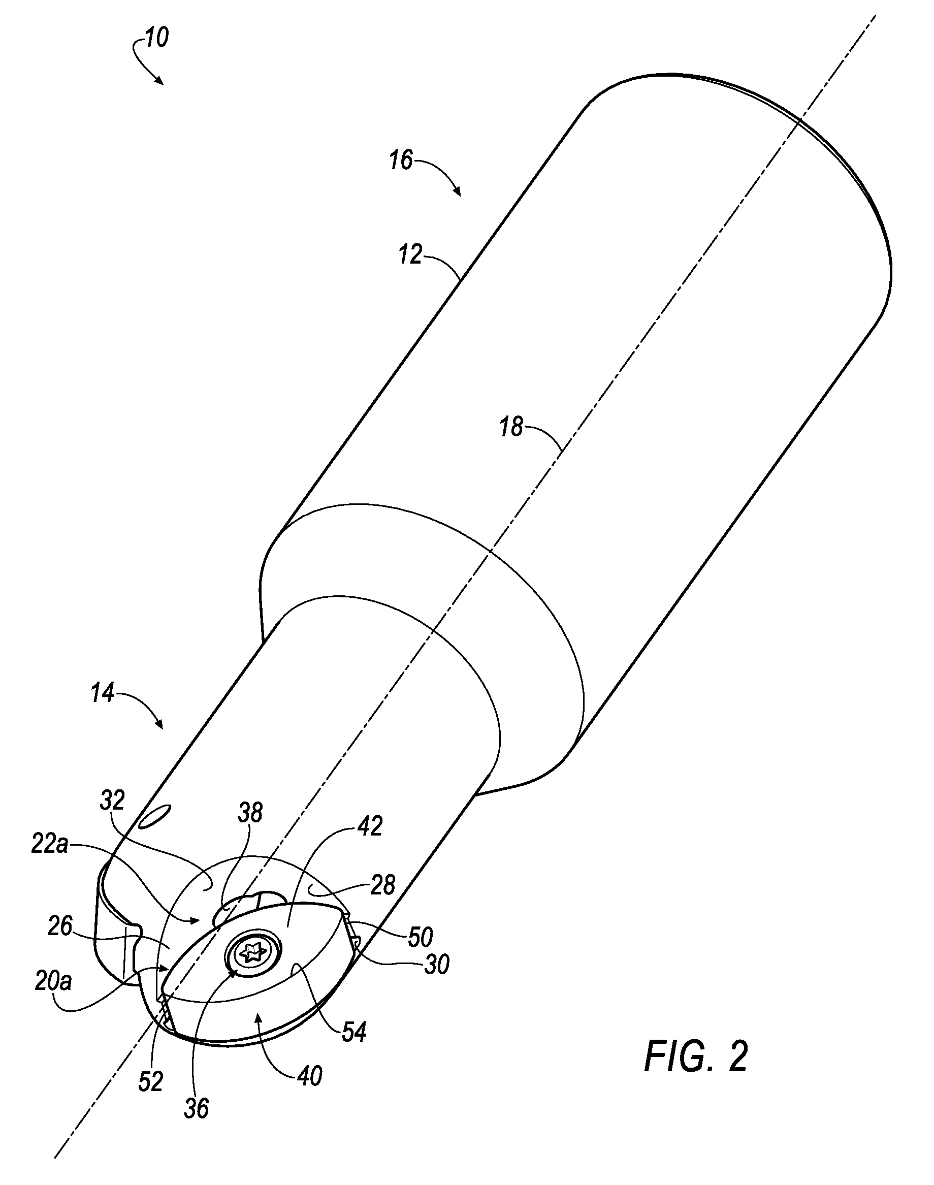
[0017]Referring now to FIGS. 1-4, a ball end mill is shown generally at 10 according to an embodiment of the invention. The ball end mill 10 includes a generally cylindrical body 12 having a generally hemispherical forward end portion 14 and a rearward end portion 16 that is adapted to be fixedly secured to a machine spindle (not shown) so that the body 12 can be rotated about an axis 18 therethrough.

[0018]The generally hemispherical forward end portion 14 may be intersectioned by two recesses, each one comprising an insert-receiving pocket 20a, 20b and a chip pocket 22a, 22b. In the illustrated embodiment, the insert-receiving pockets 20a, 20b and the chip pockets 22a, 22b are substantially identical in construction. Thus, only the insert-receiving pocket 20a and the chip pocket 22a will be described herein. The insert-receiving pocket 20a includes a bottom support surface 24, an axial side support surface 26 and a radial side support surface 28. A corner relief 30 is formed betwee...


PUM

PropertyMeasurementUnit
Shapeaaaaaaaaaa
Radiusaaaaaaaaaa
Areaaaaaaaaaaa

Abstract

A double-sided ball end mill includes a body having a generally hemispherical forward end portion and a rearward end portion. The forward end portion includes insert-receiving pockets and chip pockets. A cutting insert can be mounted within each insert-receiving pocket. The cutting insert includes a first substantially planar surface, a second substantially planar surface, a first curvilinear side surface, a second curvilinear side surface, a first pair of cutting edges formed at an intersection between the first substantially planar surface and the first and second curvilinear side surfaces, and a second pair of cutting edges formed at an intersection between the second substantially planar surface and the first and second curvilinear side surfaces. The first and second planar surfaces are substantially parallel to each other, and the cutting insert is mirror symmetric about all three axes.

Description

BACKGROUND OF THE INVENTION[0001]The invention relates in general to a cutting insert for a ball end mill, and in particular, to a double-sided cutting insert for a ball end mill having four cutting edges that can cut in any direction without the requirement of error proofing when the cutting insert is mounted on the ball end mill.[0002]Ball nose end mills are used in many metal working applications including mold making where the inherent strength and milling advantages of a fully radiused cutting edge for the copy milling of a mold cavity is best demonstrated. Its ball shape allows the end mill to attack the mold cavity from any angle or direction. The cutting edge when generated through the end of the ball mill becomes helical with rotation. This promotes shearing of the metal to be cut in an efficient manner.[0003]A conventional ball nose end mill includes a generally cylindrical end mill body having a generally hemispherical forward end portion. Two insert-receiving seats or re...

Claims


Application Information

Patent Timeline
IPC IPC(8): B26D1/12B26D1/00
CPCB23C5/1045B23C5/2221B23C2200/128Y10T407/235B23C2210/168B23C2250/12Y10T407/1924B23C2200/203B23C5/2213B23C5/22B23C5/20B23C5/10B23B27/16
Inventor MORRISON, MICHAEL G.BONTHA, SRIKANTH
Owner KENNAMETAL INC
Why Eureka
Try Eureka