Optical fiber mode couplers

a technology of optical fiber and coupler, which is applied in the direction of optics, optical waveguide light guide, instruments, etc., can solve the problems of not being very useful for applications and complicated radial dependence of the e-field of the hom optical fiber in the hom optical fiber

Active Publication Date: 2010-05-27
OFS FITEL LLC
View PDF13 Cites 28 Cited by
  • Summary
  • Abstract
  • Description
  • Claims
  • Application Information

AI Technical Summary

Problems solved by technology

A problem in some devices of this kind is that the radial dependence of the E-fields of the HOMs in the HOM o

Method used


Image

  • Optical fiber mode couplers
  • Optical fiber mode couplers
  • Optical fiber mode couplers

Examples


Embodiment Construction

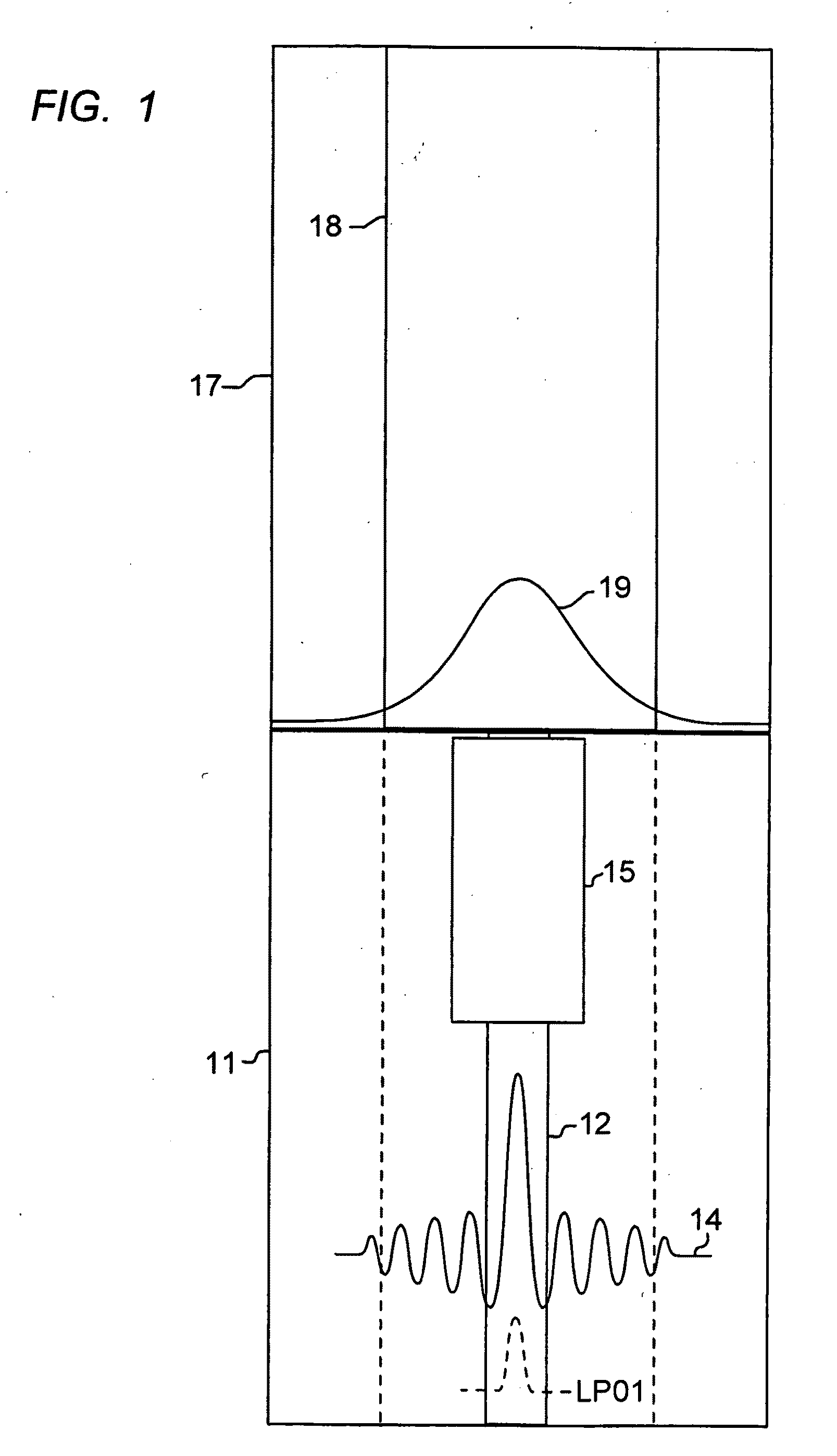
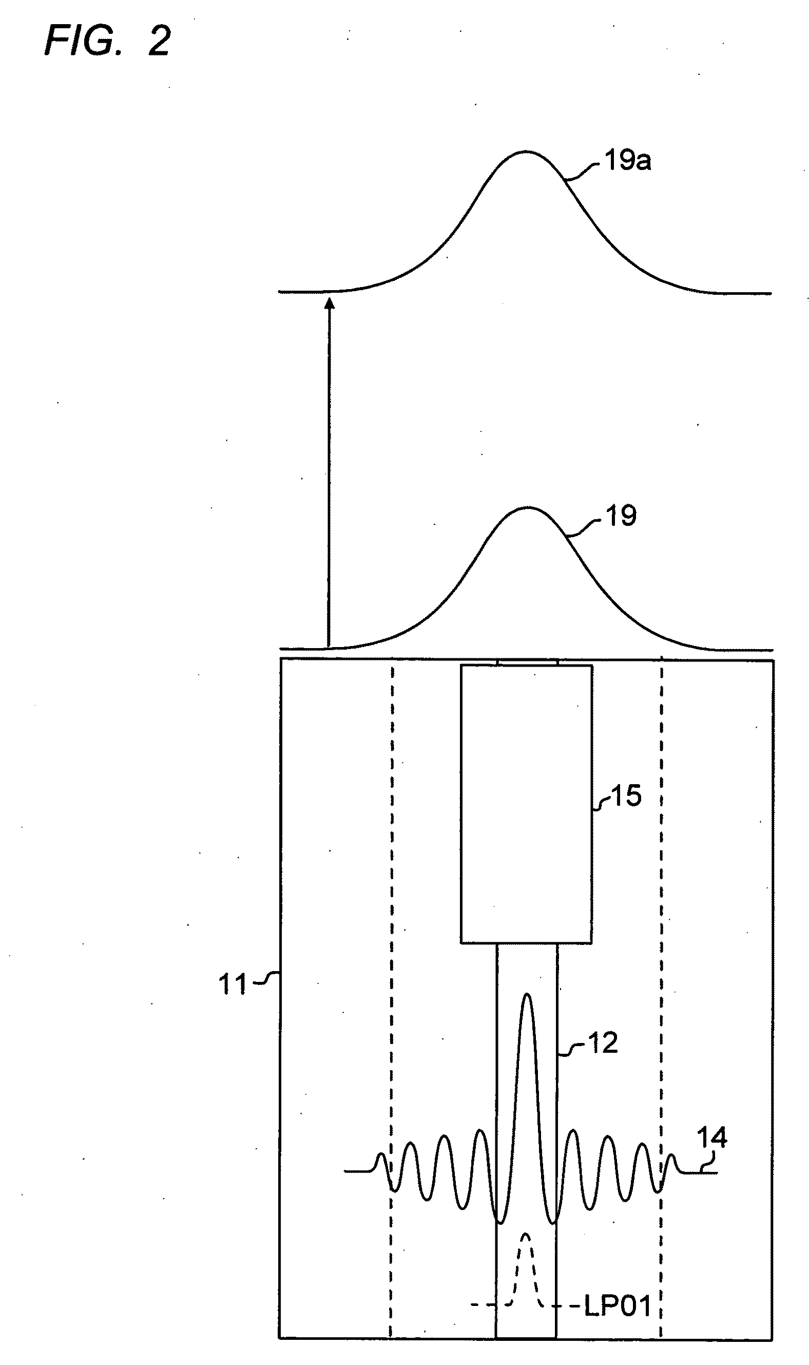
[0016]FIG. 1 is an illustration of a combination HOM optical fiber and mode transformer, coupled to a large mode area (LMA) optical fiber. The HOM optical fiber is sometimes referred to as a few mode optical fiber. The HOM optical fiber is shown at 11, with schematic HOM waveform 14 illustrating the light propagating in the core 12 of the optical fiber. A fundamental mode (LP01) is shown in phantom for comparison.

[0017]The light signal 14, or another waveform (not shown) processed to produce waveform 14, may be processed in the core of the HOM optical fiber 11. The processing may be amplification, filtering, engineered chromatic dispersion, etc. An example of processing HOMs in few mode fibers is described in U.S. Pat. No. 6,768,835, referenced above.

[0018]Referring again to FIG. 1, the light signal 14 is then converted by mode converter 15. The output 19 of the mode converter is coupled to an LMA optical fiber 17. The core of the LMA fiber is shown at 18 and, as seen, is much large...


PUM


Abstract

Described are optical devices and related methods wherein a multiple mode input in a Higher Order Mode (an HOM) optical fiber is converted by a complex mode transformer to produce a fundamental mode output in an optical medium with an E-field that is substantially different than that exiting the HOM optical fiber. The medium is preferably a Large Mode Area (LMA) optical fiber, or free space. The mode transformer may be a series of refractive index perturbations created either by photo-induced gratings or by gratings formed by physical deformations of the optical fiber.

Description

RELATED APPLICATION [0001]This application is related to application Ser. No. 12 / 157,214, filed Jun. 9, 2008, which application is incorporated herein by reference.FIELD OF THE INVENTION [0002]The invention relates to optical fiber mode controlling devices.BACKGROUND OF THE INVENTION [0003]Optical fiber and optical waveguide mode converters are well known and come in a variety of forms. They operate typically by transforming an input mode, usually a fundamental mode, into a higher order mode, or vice versa. An especially attractive mode converter device comprises a long period grating (LPG) formed in an optical fiber. See for example, U.S. Pat. No. 6,768,835, and T. Erdogan, “Fiber grating spectra,” J. Lightwave Technology vol. 15, p. 1277 (1997).[0004]These mode converters operate with a single mode input, and typically a single mode output. Propagating light in more than one mode at a time, and controllably changing the mode of more than one mode at a time, would be an attractive ...

Claims


Application Information

Patent Timeline
IPC IPC(8): G02B6/26
CPCG02B6/02066G02B6/14G02B6/02095
Inventor WESTBROOK, PAUL S.
Owner OFS FITEL LLC
Why Eureka
Try Eureka