
Battery

Active Publication Date: 2010-05-27
TOYOTA JIDOSHA KK
View PDF9 Cites 28 Cited by
  • Summary
  • Abstract
  • Description
  • Claims
  • Application Information

AI Technical Summary

Benefits of technology

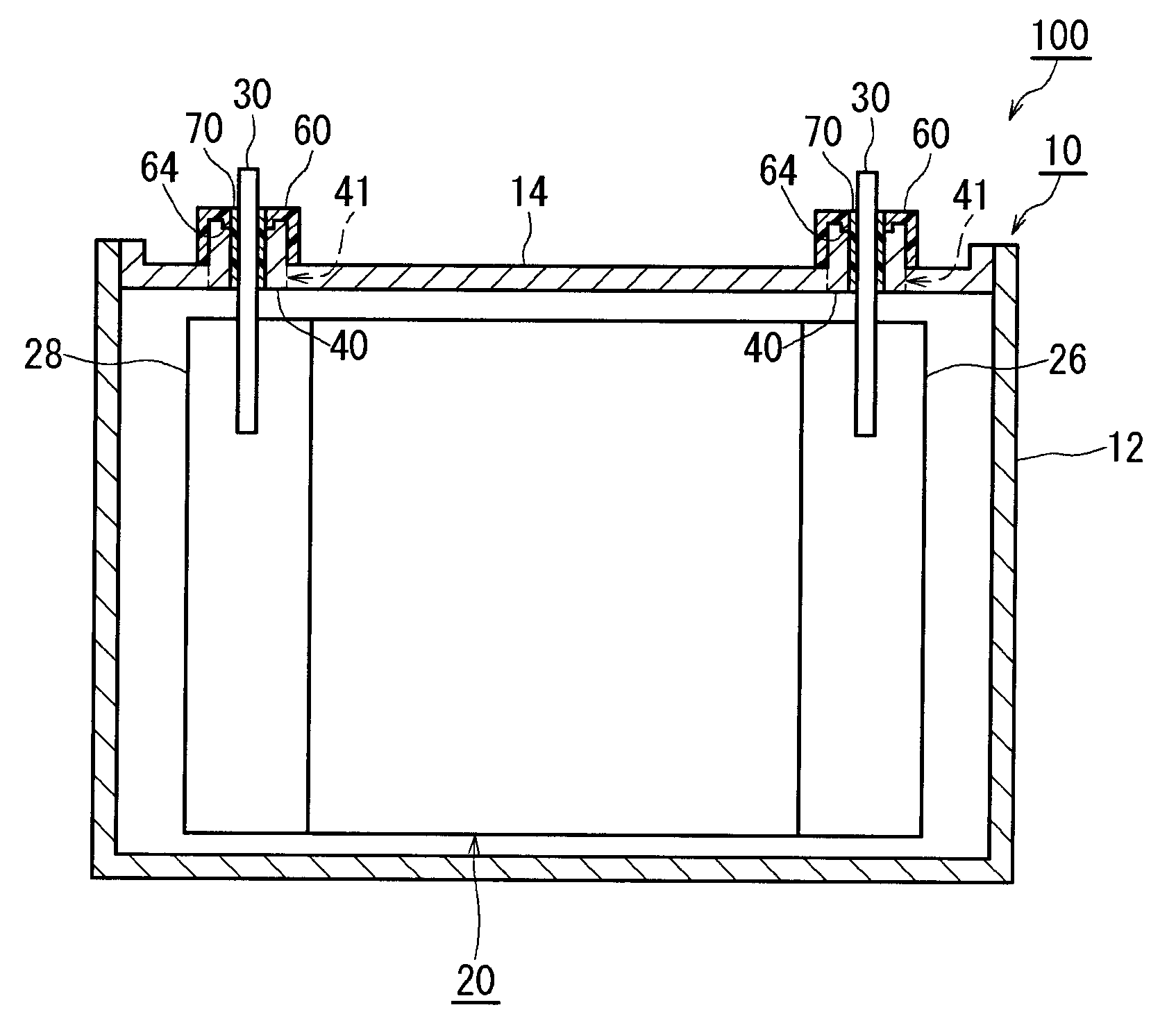
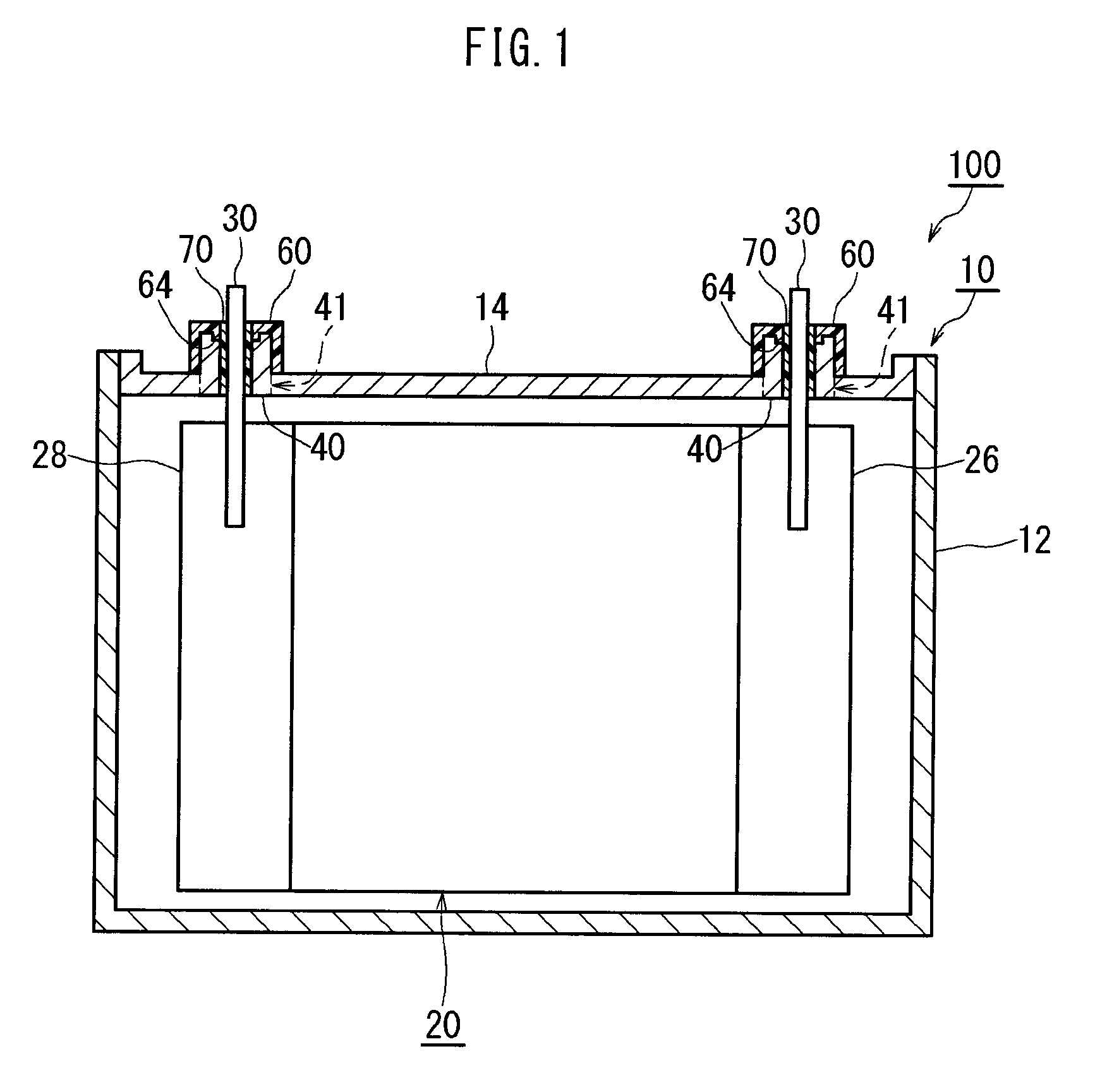
[0011]In this battery, the terminal fixing portion may be tubular, and a sealing material may be attached between an inner periphery of the terminal fixing portion and an outer periphery of the electrode terminal. Thus, the terminal fixing portion can be sealed more securely. Further, the pressure application portion may be provided on the outer cover member so as to compress against an inside edge portion of the top end portion of the terminal fixing portion. Thus, deformation can be generated in a site that is closer to the inside surface of the terminal fixing portion. Further, the pressure application portion may be constituted by a projection provided on an inner side of a ceiling portion of the outer cover member. In this case, the top end portion of the terminal fixing portion can be formed into a recess, and therefore the top end portion of the terminal fixing portion can be deformed reliably. Furthermore, an indentation may be provided in a base end portion of the projection constituting the pressure application portion. In this case, a part of the terminal fixing portion is compressed into the indentation, thereby preventing the outer cover member from becoming dislodged from the terminal fixing portion.
[0012]Further, an outer peripheral surface of the deformation restricting portion may have a reinforcing shape pattern. The strength of the deformation restricting portion can be improved by this pattern. The outer peripheral surface of the deformation restricting portion may be provided with a rib, for example. Further, the outer cover member and the terminal fixing portion may include an engaging portion that engages the outer cover member with the terminal fixing portion while the outer cover member covers the terminal fixing portion. Thus, it is possible to prevent the outer cover member from becoming dislodged from the terminal fixing portion.

Problems solved by technology

However, when this sealing structure is being applied as an electrode terminal sealing structure for battery, the electrode terminal may not be successfully fixed, depending on the battery structure.
Furthermore, there is limitation to the size of the battery case, for example, and it may be impossible to provide the site through which the electrode terminal is inserted with sufficiently thickness.

Method used


Image

  • Battery
  • Battery
  • Battery

Examples


Embodiment Construction

[0028]Embodiments of the present invention will be described below with reference to the drawings. Note that the present invention is not limited to the following embodiments. Further, constitutional elements having substantially identical functions are allocated with identical reference numerals in the drawings where appropriate. Further, dimensional relationships (length, width, thickness, and so on) in each drawing do not reflect the actual dimensional relationships. Moreover, in this specification, the battery encompasses any storage elements that can be used in a similar manner in the industrial field. Examples of the battery include lithium ion battery (lithium secondary battery), nickel hydrogen battery, nickel cadmium battery, lead battery, or the like.

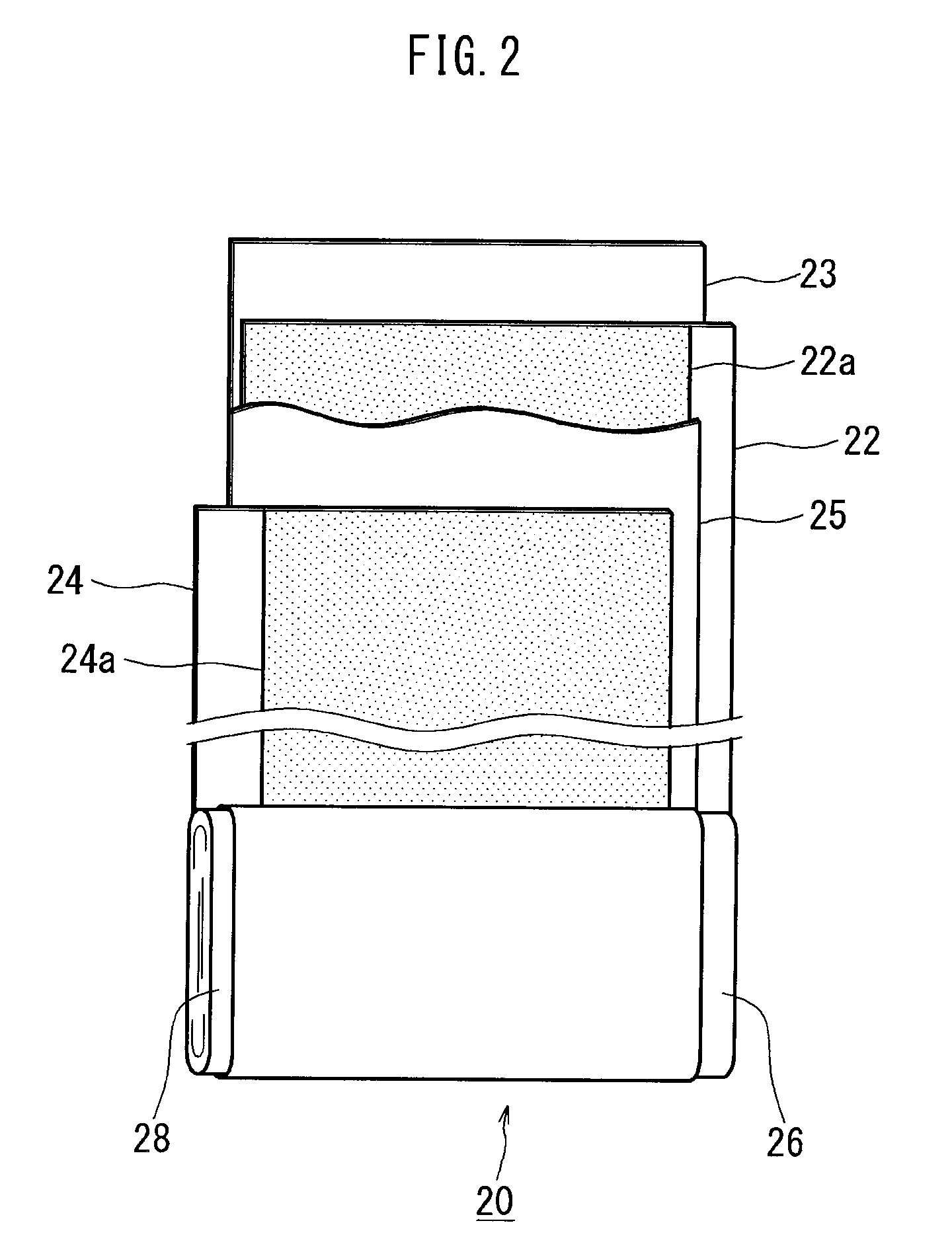
[0029]FIG. 1 is a schematic sectional view showing a battery 100 according to an embodiment of the present invention. As shown in FIG. 1, the battery 100 is constituted by a battery case 10 and an electrode body 20. As shown i...


PUM


Abstract

A battery (100) includes a terminal fixing portion (40) projecting outwardly from a lid body (14), and an outer cover member (60) covering the terminal fixing portion (40). The terminal fixing portion (40) includes a hole (42) into which an electrode terminal (30) is inserted. The outer cover member (60) includes a cylindrical portion (62) (deformation restricting portion) covering an outer peripheral surface (40b) of the terminal fixing portion (40) and restrict deformation of the outer peripheral surface (40b) of the terminal fixing portion (40), and a pressure application portion (64) that compresses against a top end portion (40a) of the terminal fixing portion (40) and causes the terminal fixing portion (40) to deform.

Description

BACKGROUND OF THE INVENTION[0001]1. Field of the Invention[0002]The present invention relates to a battery, and more particularly to a battery in which an electrode terminal is fixed to a battery case in an inserted state. Note that this application claims priority under the Paris Convention based on Japanese Patent Application 2008-302624, filed on Nov. 27, 2008, the entire contents of which are incorporated into this application by reference.[0003]2. Description of the Related Art[0004]In recent years, lithium ion batteries, nickel hydrogen batteries, and other secondary batteries have grown in importance as power supplies installed in vehicles or power supplies for personal computers and portable terminals. These batteries are structured such that an electrode body is accommodated in a battery case. An electrode terminal is fixed to the battery case in an inserted state, and the electrode terminal is connected to the electrode body in the interior of the battery case.[0005]Method...

Claims


Application Information

Patent Timeline
IPC IPC(8): H01M2/02H01M50/103H01M50/176H01M50/55H01M50/553H01M50/567
CPCH01M2/024H01M2/06H01M2/30H01M2/347H01M2/021H01M2/305Y02E60/10H01M50/579H01M50/103H01M50/567H01M50/55H01M50/553H01M50/176
Inventor MATSUBARA, MASANORI
Owner TOYOTA JIDOSHA KK
Learn More