
Dynamic observer for the estimation of vehicle lateral velocity

a dynamic observer and vehicle lateral velocity technology, applied in the field of system and method for estimating vehicle lateral velocity, can solve the problems of inability to assume that all drivers would know when and how to counter-steer the vehicle out, less responsive steering input, and difficult control for the driver

Active Publication Date: 2010-05-27
GM GLOBAL TECH OPERATIONS LLC
View PDF8 Cites 34 Cited by
  • Summary
  • Abstract
  • Description
  • Claims
  • Application Information

AI Technical Summary

Problems solved by technology

The estimation of the surface coefficient of friction based on a lateral acceleration is typically not robust relative to a banked curve because of the gravity bias effect on the body mounted lateral accelerometer.
Current production yaw stability control systems do not rely directly on feedback control of lateral velocity or side-slip angle estimates because a production level robust and accurate estimate of lateral velocity has not been fully developed.
However, production yaw stability control systems do utilize an estimate of a vehicle's lateral velocity to influence or modify the yaw-rate error used for feedback control.
In general, there are dynamic conditions in which the vehicle develops a side-slip angle that the yaw stability controller will not detect and stabilize.
When the vehicle develops large side-slip angles, it becomes less responsive to steering input and more difficult for the driver to control.
While such maneuvers might seem unreasonable because they require the driver not to correct a possible vehicle over-steer behavior, it cannot be assumed that all drivers would know when and how to counter-steer the vehicle out of the unstable condition.
Any instance in which the vehicle's side-slip angle increases to a relatively large level for a given surface the driver may have trouble controlling the vehicle.

Method used


Image

  • Dynamic observer for the estimation of vehicle lateral velocity
  • Dynamic observer for the estimation of vehicle lateral velocity
  • Dynamic observer for the estimation of vehicle lateral velocity

Examples


Embodiment Construction

[0016]The following discussion of the embodiments of the invention directed to a system and method for estimating surface coefficient of friction is merely exemplary in nature, and is in no way intended to limit the invention or its applications or uses. For example, the discussion below concerns estimating surface coefficient of friction for a vehicle system. However, as will be appreciated by those skilled in the art, the coefficient of friction estimation system may have other applications.

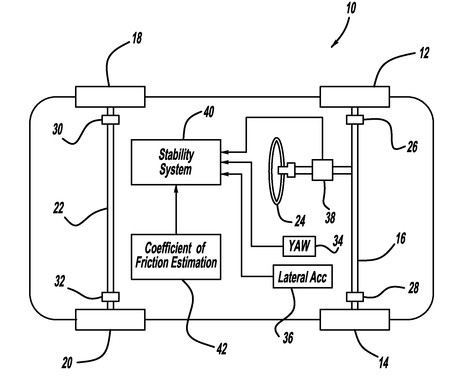
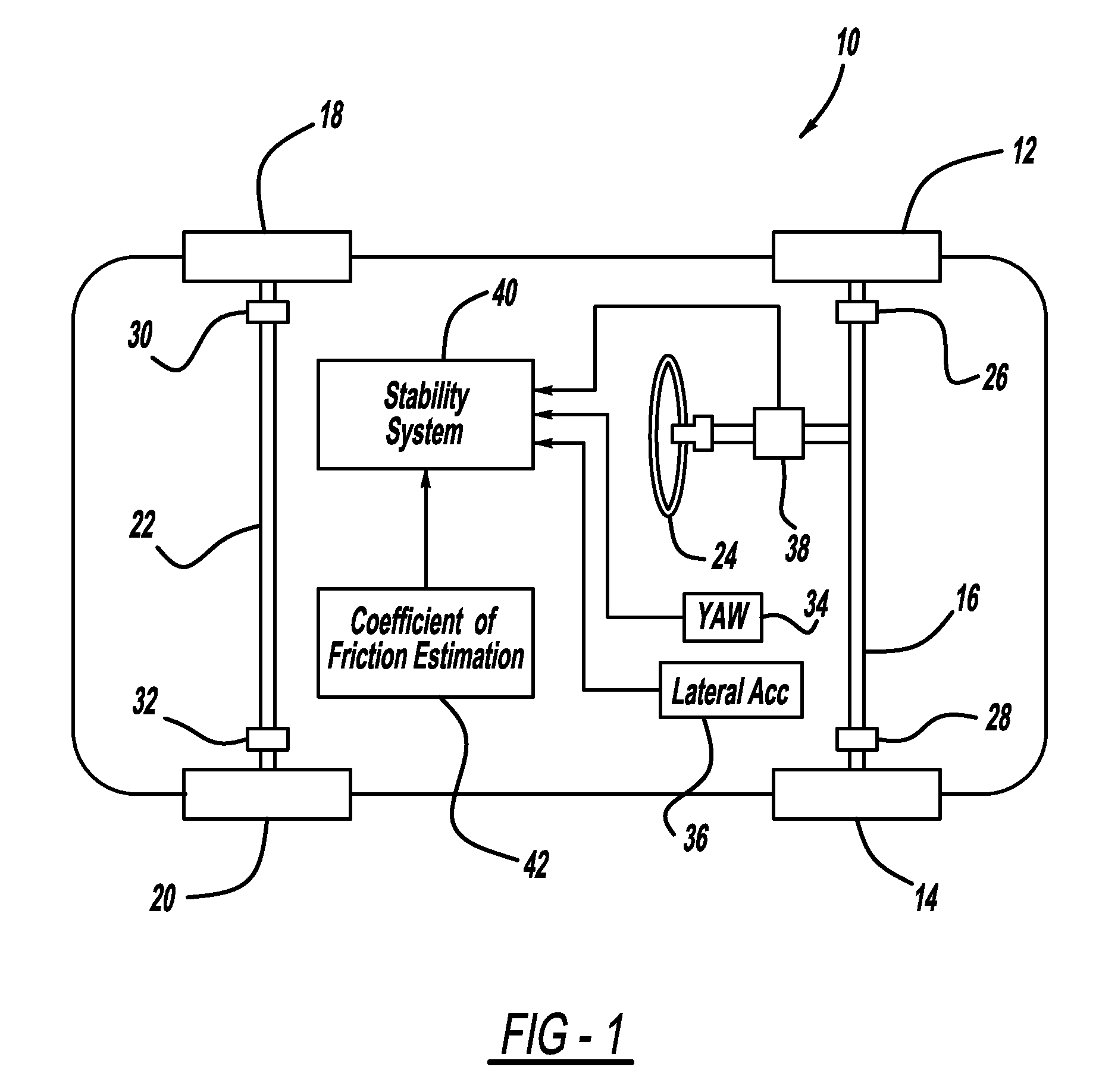
[0017]FIG. 1 is a plan view of a vehicle 10 including front wheels 12 and 14 connected by a front axle 16 and rear wheels 18 and 20 connected by a rear axle 22. A steering wheel 24 steers the front wheels 12 and 14. A wheel speed sensor 26 measures the speed of the front wheel 12, a wheel speed sensor 28 measures the speed of the front wheel 14, a wheel speed sensor 30 measures the speed of the rear wheel 18 and a wheel speed sensor 32 measures the speed of the rear wheel 20. A yaw-rate sensor ...


PUM


Abstract

A system and method for estimating vehicle lateral velocity that defines a relationship between front and rear axle lateral forces and front and rear axle side-slip angles. The method includes providing measurements of vehicle yaw-rate, lateral acceleration, longitudinal speed, and steering angle. The method also includes using these measurements to provide a measurement of the front and rear axle forces. The method calculates a front axle lateral velocity and a rear axle lateral velocity, and calculates a front axle side-slip angle based on the rear axle lateral velocity and a rear axle side-slip angle based on the front axle lateral velocity. The method then estimates front and rear axle forces, and selects a virtual lateral velocity that minimizes an error between the estimated and measured lateral axle forces. The method then provides an estimated vehicle lateral velocity using the selected virtual lateral velocity.

Description

BACKGROUND OF THE INVENTION[0001]1. Field of the Invention[0002]This invention relates generally to a system and method for estimating vehicle lateral velocity and, more particularly, to a system and method for estimating vehicle lateral velocity that employs a dynamic observer for relating front and rear axle lateral forces to front and rear axle side-slip angles.[0003]2. Discussion of the Related Art[0004]Vehicle stability control systems are known in the art to enhance vehicle stability in the event that the system detects that the vehicle may not be operating as the driver intends. For example, on an icy or snowy surface, the driver may steer the vehicle in one direction, but the vehicle may actually travel in another direction. Signals from various sensors, such as yaw-rate sensors, hand-wheel angle sensors, lateral acceleration sensors, etc., can detect the vehicle instability. Calculations made by these types of vehicle stability control systems often require an estimation of...

Claims


Application Information

Patent Timeline
IPC IPC(8): G01P3/00G06F15/00
CPCB60T8/172B60T2250/04B60T2230/02B60T2210/22
Inventor NARDI, FLAVIORYU, JIHANMOSHCHUK, NIKOLAI K.O'DEA, KEVIN A.
Owner GM GLOBAL TECH OPERATIONS LLC
Learn More