Ball screw device having tunnel raceway, and method for manufacturing the same

Active Publication Date: 2010-06-03
ABOM
View PDF26 Cites 12 Cited by
  • Summary
  • Abstract
  • Description
  • Claims
  • Application Information

AI Technical Summary

Benefits of technology

[0053]Feature (7): The number of component parts is reduced, and a simpl

Problems solved by technology

Using such a tool having an outer diameter less than that of the ball (27) makes the procedure difficul

Method used


Image

  • Ball screw device having tunnel raceway, and method for manufacturing the same
  • Ball screw device having tunnel raceway, and method for manufacturing the same
  • Ball screw device having tunnel raceway, and method for manufacturing the same

Examples


first embodiment

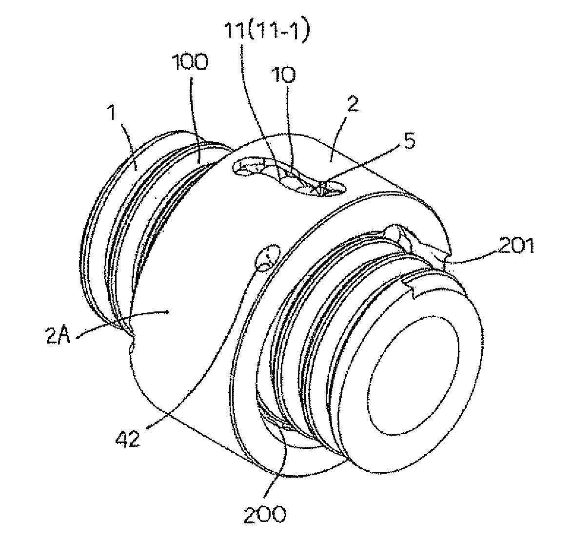
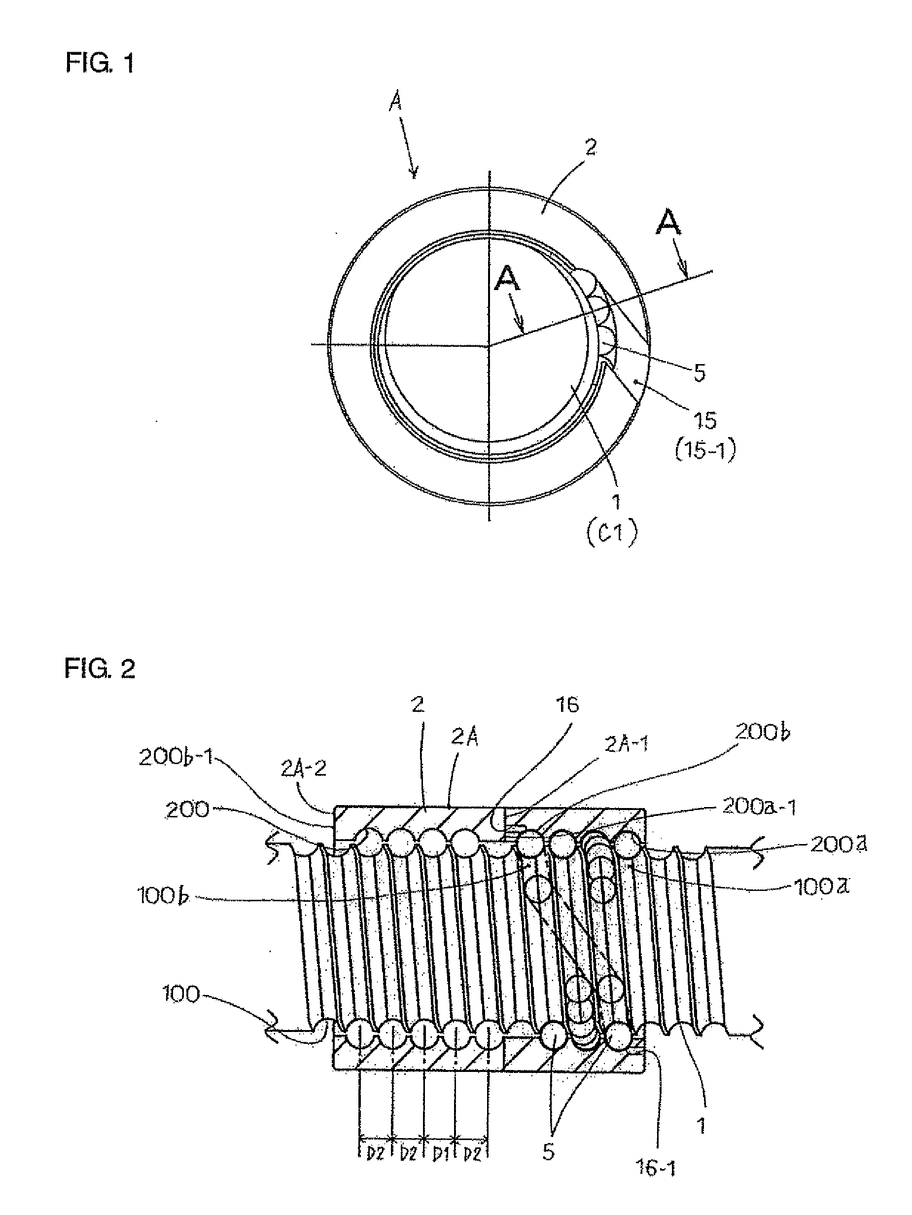
[0130]In this invention, or on the outer circumference of the other side of the rack shaft C1, a screw axis 1 is formed on a ball screw device A. Also, the ball screw device A, as shown in FIGS. 1 and 2, comprises a screw axis 1 having a helical groove 100 on its outer circumference, and a nut 2 having a helical groove 200 on its inner circumference, and balls 5 to circulate in an orbit 3 formed by the joined helical groove 100 of the screw axis 1 and the helical groove 200 of the nut 2, thus forming a tunnel raceway 6 allowing for the balls to circulate unlimitedly from one end 200a of the helical groove 200 of the nut 2 to the other end 200b of the helical groove 200 of the nut 2.

[0131]Appropriate pressure is provided between the helical groove 100 of the screw axis 1 and the helical groove 200 of the nut 2, along which the balls 5 circulates. When the rotation of the screw axis 1 is regulated, and a pair of nuts 2 are connected, while the rotation of the nuts 2 are regulated, and...

fourth embodiment

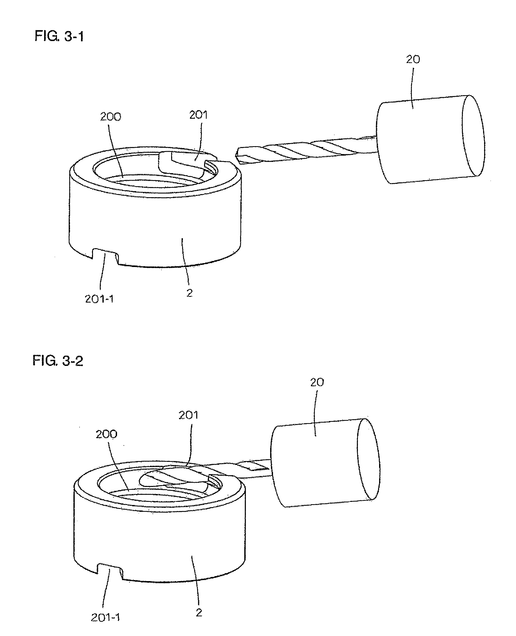
[0144]In this invention, if the land portion 203 cannot be provided due to the lack of a helical cut-out groove 200, and the processing tool which cannot be suspended in the middle of the cutting process is used, the cut-out 40 is formed on the orbit 3 (helical groove 100, 200), on the access way 30, 30-1, or on the helical cut-out groove 201. Therefore, the cut-out 40 should be filled with material, so as to restore the original structure. In the drawing, when the cut-out 40 is formed on the helical cut-out groove 201, a filler material 41 is inserted into the cut-out 40 to fill it. (FIGS. 5-1 to 5-3 show the structure in which the projection 22 in the shape of a scale is provided on the guidepath 11, 11-1.) Furthermore, another example is described here. Although the processing tool described above is preferable, other processing tools can be used for covering (blocking) the process error or for making the end 200a-1, or the like, of the nut 2 flat. Other examples are pursuant to ...


PUM

PropertyMeasurementUnit
Angleaaaaaaaaaa
Diameteraaaaaaaaaa
Circumferenceaaaaaaaaaa

Abstract

A ball screw device of a screw axis with a helical groove on its outer circumference for balls to circulate thereon includes a nut with a helical groove on its inner circumference for balls to circulate thereon, a number of balls to circulate in an orbit along the helical groove of the screw axis and the helical groove of the nut, and a tunnel raceway for the balls to circulate unlimitedly. The device has a through-hole formed within the wall of the nut for the balls to circulate from one end of the helical groove to the other end, the through-hole having a guidepath on either end of the helical groove to feed the balls into the tunnel raceway. Means are provided between the helical groove on one end face of the nut and the helical groove on the screw axis to prevent the balls from exiting either helical groove.

Description

FIELD OF INVENTION[0001]This application claims priority based on Japanese Patent Application No. JP2007-62020, filed on Mar. 12, 2007, entitled “Ball Screw Device Having A Circuit, and Method for Manufacturing the Same.”TECHNICAL BACKGROUND[0002]Normally, in the case where an electric motor is used to generate motive energy for translational movement, a ball screw device (including a screw drive transmission device) is used to change the rotary movement of the electric motor to one of translational movement.[0003]The example of the ball screw device is a structure comprising a screw axis, with the outer circumference being a helical-shaped groove (hereinafter referred to as “helical groove”) in which for the balls of the device can roll and move, with a nut having a helical groove on the inner circumference screwed onto the screw axis, thus allowing the balls to roll and move in an aligned orbit formed by the groove of the screw axis and not opposed to each other, thus forming a ci...

Claims


Application Information

Patent Timeline
IPC IPC(8): F16H25/22B23P17/00
CPCF16H25/2223Y10T74/19772Y10T29/49F16H2025/2481F16H25/2214Y10T74/19767F16H25/20F16H25/22
Inventor SUGITA, SENTAROU
Owner ABOM
Why Eureka
Try Eureka