Chemical and biological protection mask

a technology of biological protection mask and chemical mechanism, which is applied in the direction of breathing mask, breathing filter, breathing protection, etc., can solve the problems of distorted dna molecules, difficult to incorporate chemical mechanisms into gas masks, and insufficient filtering effect of biological organisms

Active Publication Date: 2010-06-03
PHOENIX TECHNOLOGIES LTD
View PDF7 Cites 45 Cited by
  • Summary
  • Abstract
  • Description
  • Claims
  • Application Information

AI Technical Summary

Benefits of technology

[0015]It is another object of the present invention to provide a combination chemical and biological protection mask with a miniaturized low-power UV LED-light array
[0016]These and other objects are achieved herein by a gas mask or respirator that combines a filter cartridge with a miniaturized high-intensity shortwave UV disinfecting system in a compact easy-to-wear and fully portable form factor. The gas mask comprises a mask portion for covering at least the nose and mouth of a user, a one way exhalation valve mounted on the mask portion, a coupling to an inhalation opening into the mask portion, a filter canister, and a novel UV-illumination tube attachable between the inhalation valve coupling and filter canister. The UV illumination tube furthe

Problems solved by technology

Despite their effectiveness against particulate materials and suspensions, the foregoing and other known filter-type gas masks are not sufficiently effective in filtering biological organisms such as viruses and germs.
However, it particularly difficult to incorporate chemical mechanisms into a gas mask.
Germicidal ultraviolet (UVC) light kills cells by damaging their DNA.
Ultraviolet photons harm the DNA molecules

Method used


Image

  • Chemical and biological protection mask
  • Chemical and biological protection mask
  • Chemical and biological protection mask

Examples


Embodiment Construction

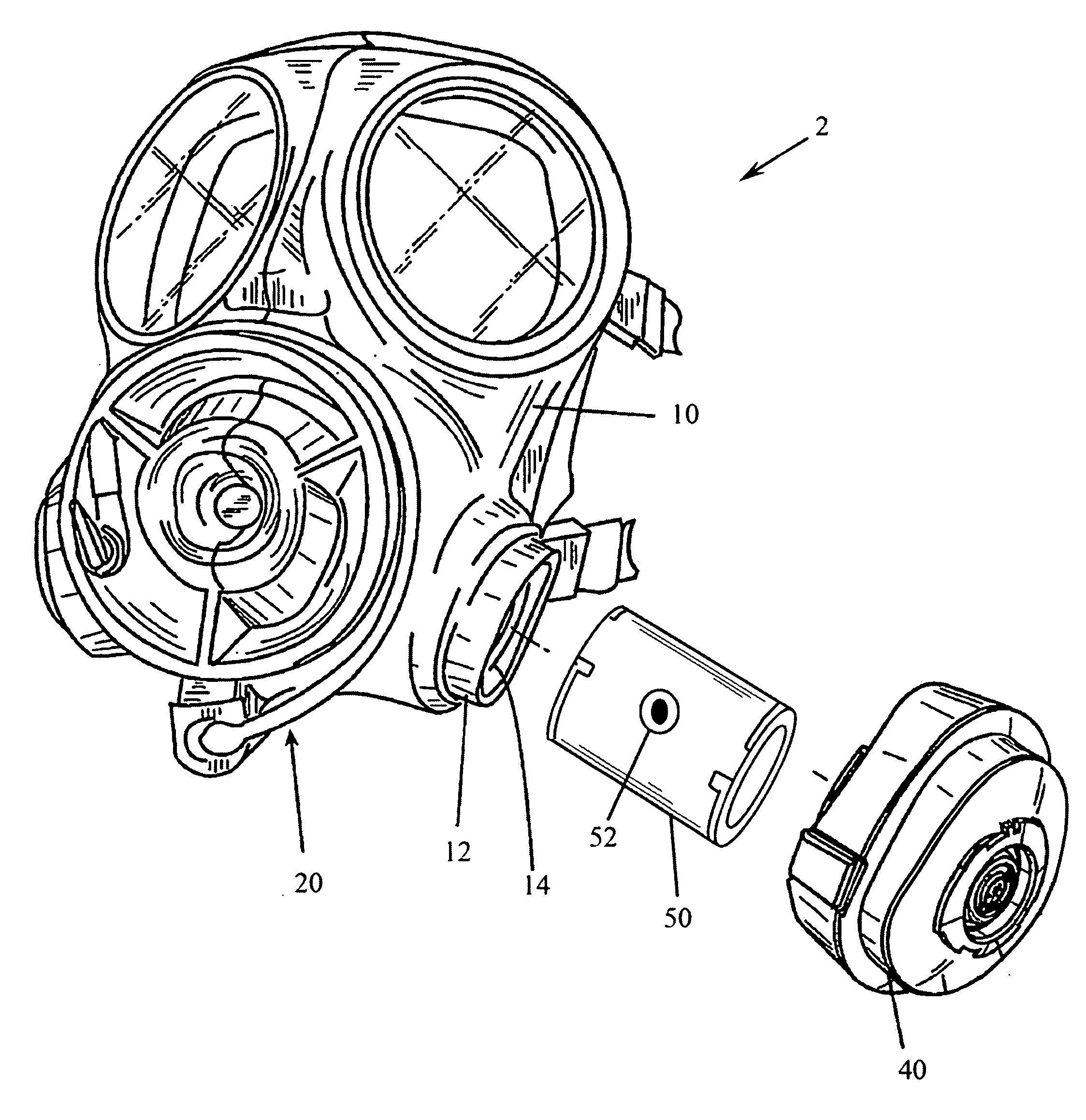
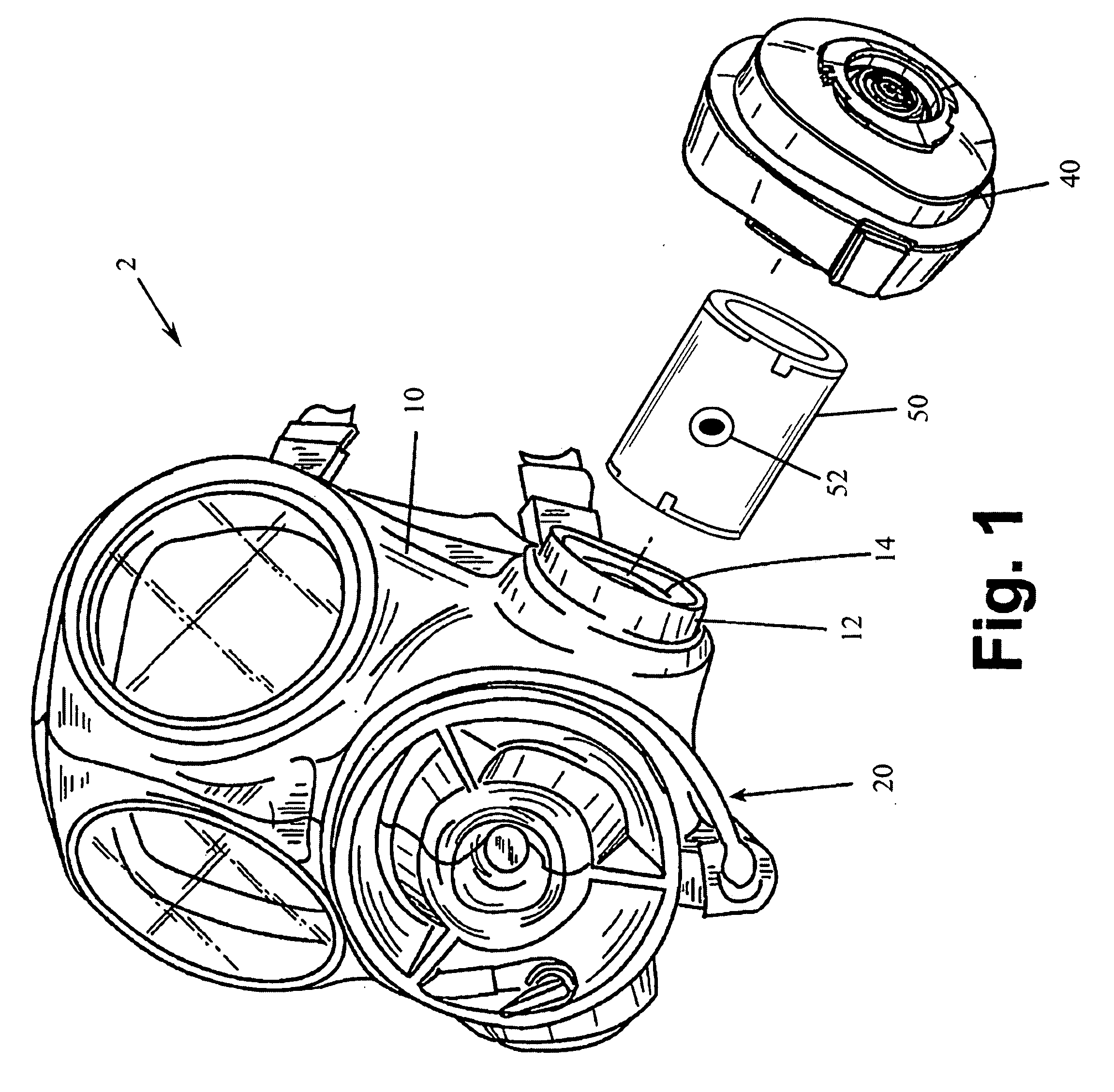
[0022]The present invention is a chemical and biological protection mask that combines a filter cartridge with a miniaturized high-intensity shortwave UV disinfecting system in a compact easy-to-wear and fully portable form factor.

[0023]FIG. 1 is a front perspective view of the gas mask assembly 2 according to an embodiment of the present invention. The gas mask assembly 2 generally comprises a molded mask portion 10 containing a frontal one-way exhalation valve 20 and one or more adjacent inhalation apertures 12. In the illustrated embodiment, the inhalation aperture 12 is equipped with a push-and-twist receptacle 14. In the prior art, a filter assembly 40 with a mating push-and-twist seat would be inserted directly into receptacle 14 to provide mechanical filtration capabilities, such as HEPA-type or charcoal filters. All the aforementioned components are known in the art and readily available. As an example, AVON Rubber's Protection Division produces a variety of suitable full an...


PUM


Abstract

A chemical and biological protection mask that combines a filter cartridge with a miniaturized high-intensity shortwave UV disinfecting system in a compact easy-to-wear and fully portable form factor. The gas mask comprises a mask portion for covering at least the nose and mouth of a user, a one way exhalation valve mounted on the mask portion, a coupling to an inhalation opening into the mask portion, a filter canister, and a novel UV-illumination tube attachable between the inhalation valve coupling and filter canister. The UV-illumination tube further comprises an aluminum tube, a plastic insert positioned inside the aluminum tube, and a plurality of circuit boards seated within the insert. The circuit boards each have a plurality of UV LED lights axially mounted thereon to irradiate and disinfect air passing through the UV-illumination tube. The UV LED lights preferably emit light within a range of from 240 nm˜280 nm wavelength, and are powered by a battery connected to a voltage regulator. A current chopping circuit is connected between said voltage regulator and said UV LED lights for providing pulsed current thereto. An optional solar cell is disclosed for powering the UV LED lights directly or for recharging the battery, and the solar cell may be mounted atop a visor attached to said mask.

Description

CROSS-REFERENCE TO RELATED APPLICATION(S)[0001]The present application is a continuation-in-part of U.S. application Ser. No. 12 / 385,482 filed 9 Apr. 2009, and derives priority from U.S. provisional application Ser. No. 61 / 193,432 filed Nov. 28, 2008.BACKGROUND OF THE INVENTION[0002]1. Field of the Invention[0003]The present invention relates to protective breathing devices, and, more particularly, to a chemical and biological protection mask that combines a filter cartridge with a miniaturized high-intensity shortwave UV disinfecting system.[0004]2. Description of the Background[0005]There is a wide variety of prior art with regard to gas masks and breathing gas respirators. Most conventional gas mask / respirators utilize a half-mask or full face mask that covers the nose and mouth and in the latter case the entire upper face.[0006]Gas masks as described above use a face piece made of an impermeable material, resistant to chemical agents and a harness which allows the mask to be put...

Claims


Application Information

Patent Timeline
IPC IPC(8): A62B18/02A62B9/00
CPCA62B7/10A62B23/02A62B18/08A61L9/20
Inventor LITZ, JEFFREY C.
Owner PHOENIX TECHNOLOGIES LTD
Why Eureka
Try Eureka