Method for assembling jointed wind turbine blade

a wind turbine and blade technology, applied in the field of wind turbine blades, can solve the problems of increasing the length of the wind turbine blade, incurring significant costs, and increasing the difficulty of transportation,

Active Publication Date: 2010-06-03
GENERAL ELECTRIC CO
View PDF10 Cites 88 Cited by
  • Summary
  • Abstract
  • Description
  • Claims
  • Application Information

AI Technical Summary

Problems solved by technology

Transporting lengthy wind turbine blades to a field site incurs significant costs.
As the capacity of wind turbines i...

Method used


Image

  • Method for assembling jointed wind turbine blade
  • Method for assembling jointed wind turbine blade
  • Method for assembling jointed wind turbine blade

Examples


Embodiment Construction

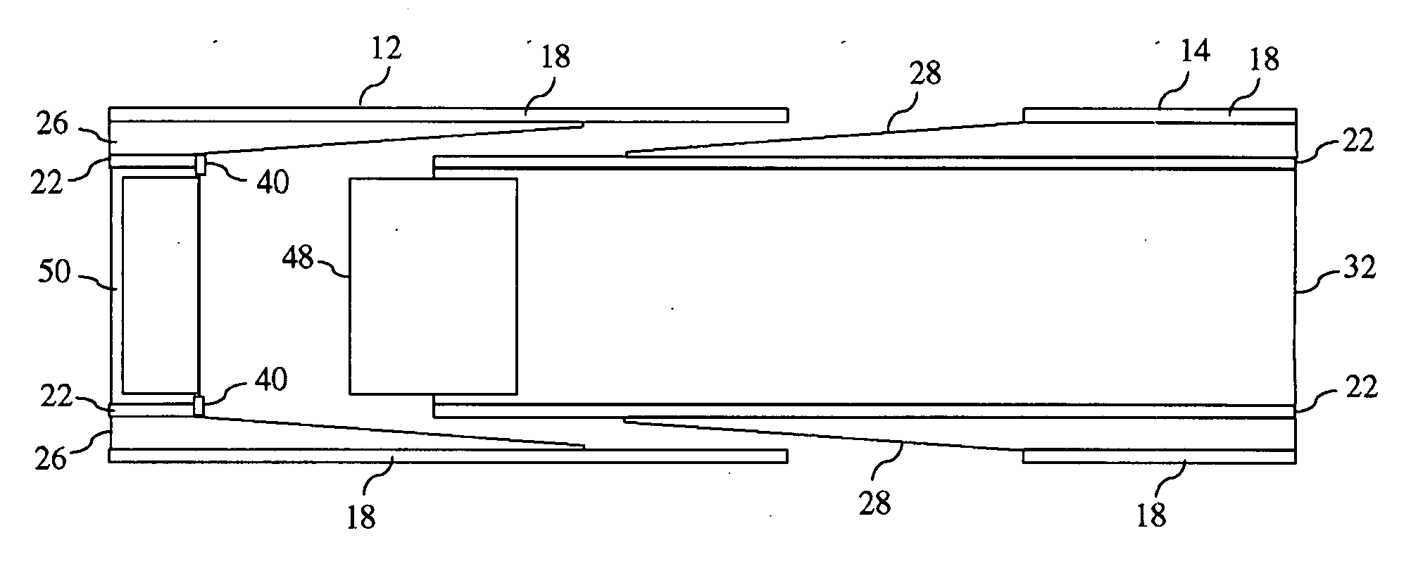
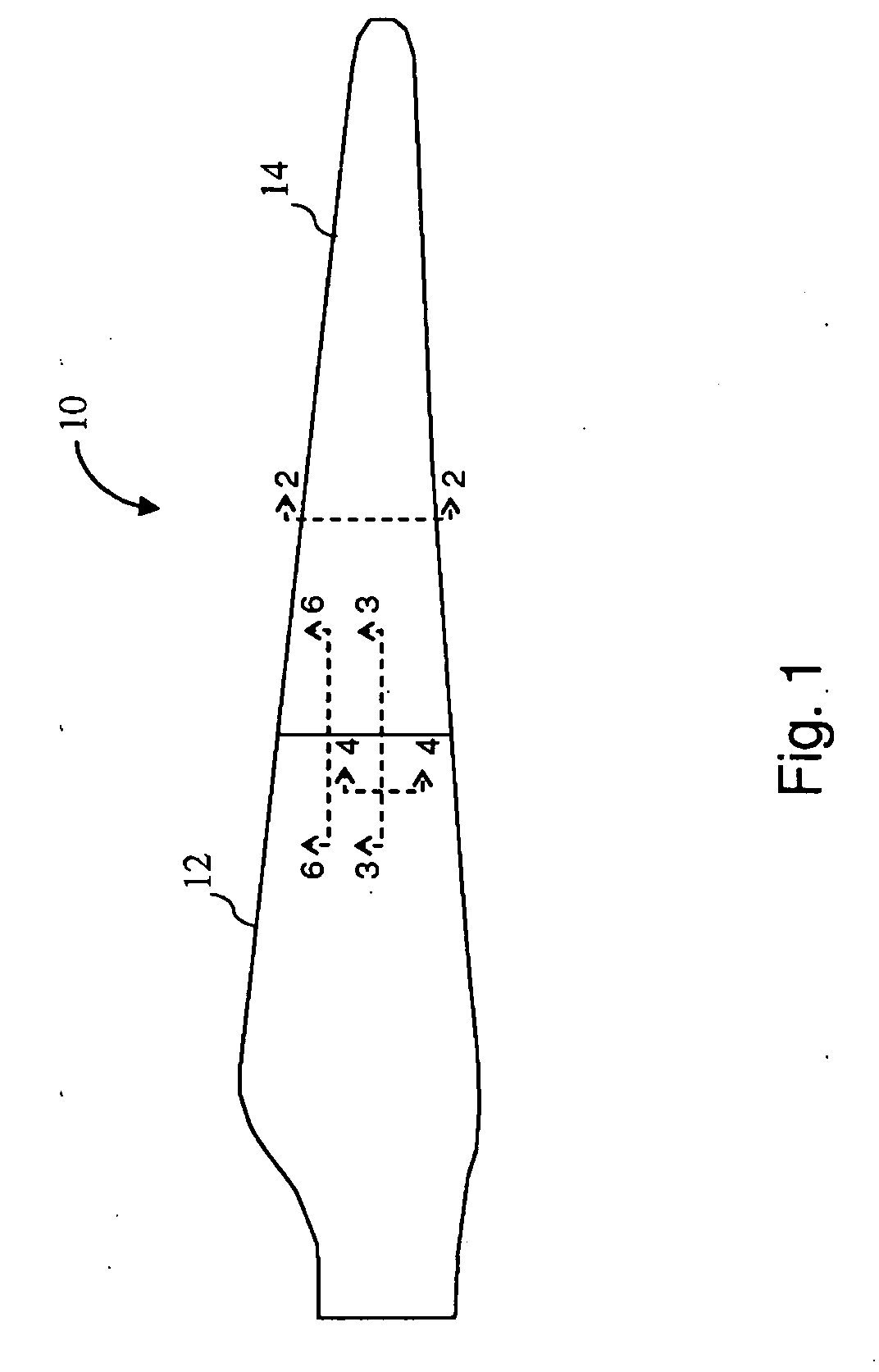
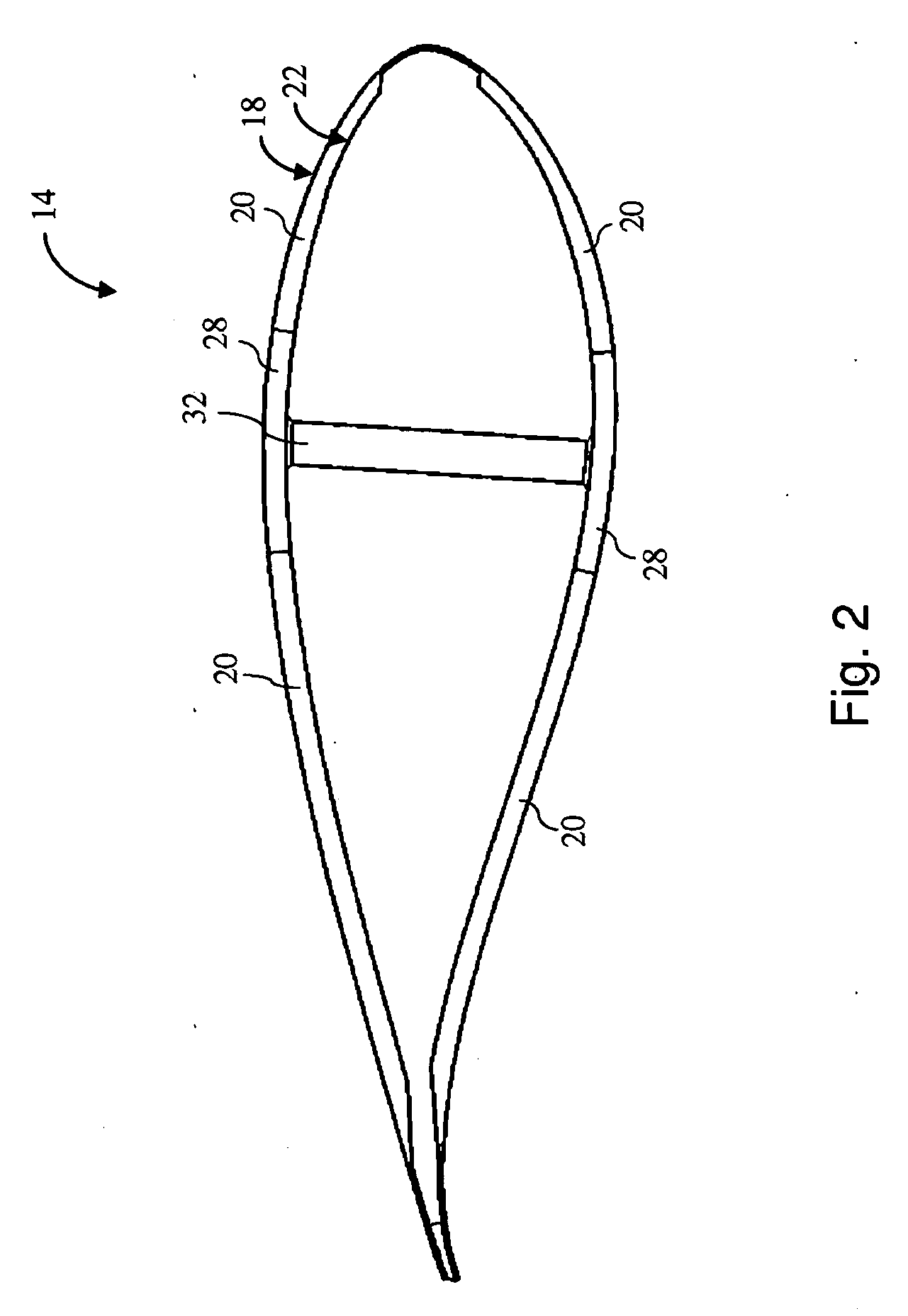
[0015]Embodiments disclosed herein include methods of assembling a jointed wind turbine blade. The methods allow transport of blade components to a secondary site or field site where the components can be assembled to form the turbine blade. Referring to FIGS. 1, 2 and 3, a wind turbine blade 10 includes a first blade segment 12 and a second blade segment 14. The first and second blade segments 12 and 14 are each hollow segments comprising an outer skin 18, skin core 20, and inner skin 22. The outer skin 18, skin core 20, and inner skin 22 are made from materials that are light-weight and strong.

[0016]The first blade segment 12 includes at least two first spar cap segments 26, and the second blade segment 14 includes at least two second spar cap segments 28. The first and second spar cap segments are configured to form a scarf joint therebetween. A shear web 32 connects the first spar cap segments 26 in the first blade segment 12. Similarly, a shear web 32 connects the second spar c...


PUM

PropertyMeasurementUnit
Timeaaaaaaaaaa

Abstract

A method of assembling a wind turbine blade comprises providing a first blade segment comprising at least two first spar cap segments; providing a second blade segment comprising at least two second spar cap segments; inserting the second blade segment into the first blade segment wherein a spar cap cavity is formed between each set of corresponding first and second spar cap segments; injecting an adhesive into the spar cap cavities to bond the blade segments together, wherein a scarf joint is formed between each set of corresponding first and second spar cap segments.

Description

FIELD OF THE INVENTION[0001]This disclosure relates to a wind turbine blade and methods of assembly thereof.BACKGROUND OF THE INVENTION[0002]The subject matter disclosed herein relates generally to wind turbine blades, and more particularly, to a multi-segment wind turbine blade with at least two blade segments and a method of assembling the at least two blade segments.[0003]Transporting lengthy wind turbine blades to a field site incurs significant costs. As the capacity of wind turbines increases, the lengths of the wind turbine blades also increase, further adding to difficulties and costs of transportation. Therefore, there is a need for a wind turbine blade comprising multiple blade segments and a method of assembling the blade segments. The blade segments can be transported to the field site at lower costs and assembled to form the wind turbine blade.BRIEF SUMMARY OF THE INVENTION[0004]In accordance with one embodiment disclosed herein, a method of assembling a wind turbine bl...

Claims


Application Information

Patent Timeline
IPC IPC(8): B32B37/12B29C65/54
CPCB29C65/542Y10T29/49336B29C66/114B29C66/1142B29C66/116B29C66/721B29K2105/04B29K2105/06B29K2307/00B29K2309/08B29L2009/00B29L2031/082B29L2031/085B29L2031/7504F03D1/0675F05B2240/302Y02E10/721B29C66/1122B29C66/727B29C65/483B29C66/543B29C66/54B29C65/00B29C66/7212B29C66/723B29C66/72323B29C66/72326B29C66/72329Y02E10/72Y02P70/50B29K2307/04
Inventor BAEHMANN, PEGGY LYNNMIEBACH, THOMASTELFEYAN, ERIC JOHNLIN, WENDY WEN-LINGYERRAMALLI, CHANDRA SEKHERQUEK, SHU CHING
Owner GENERAL ELECTRIC CO
Why Eureka
Try Eureka