Vibration control equipment
- Summary
- Abstract
- Description
- Claims
- Application Information
AI Technical Summary
Benefits of technology
Problems solved by technology
Method used
Image
Examples
first embodiment
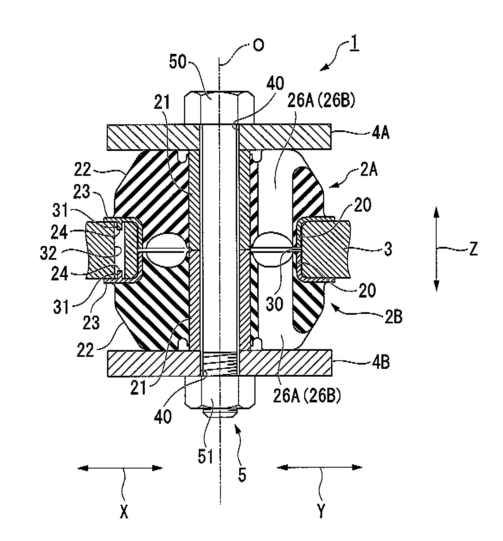
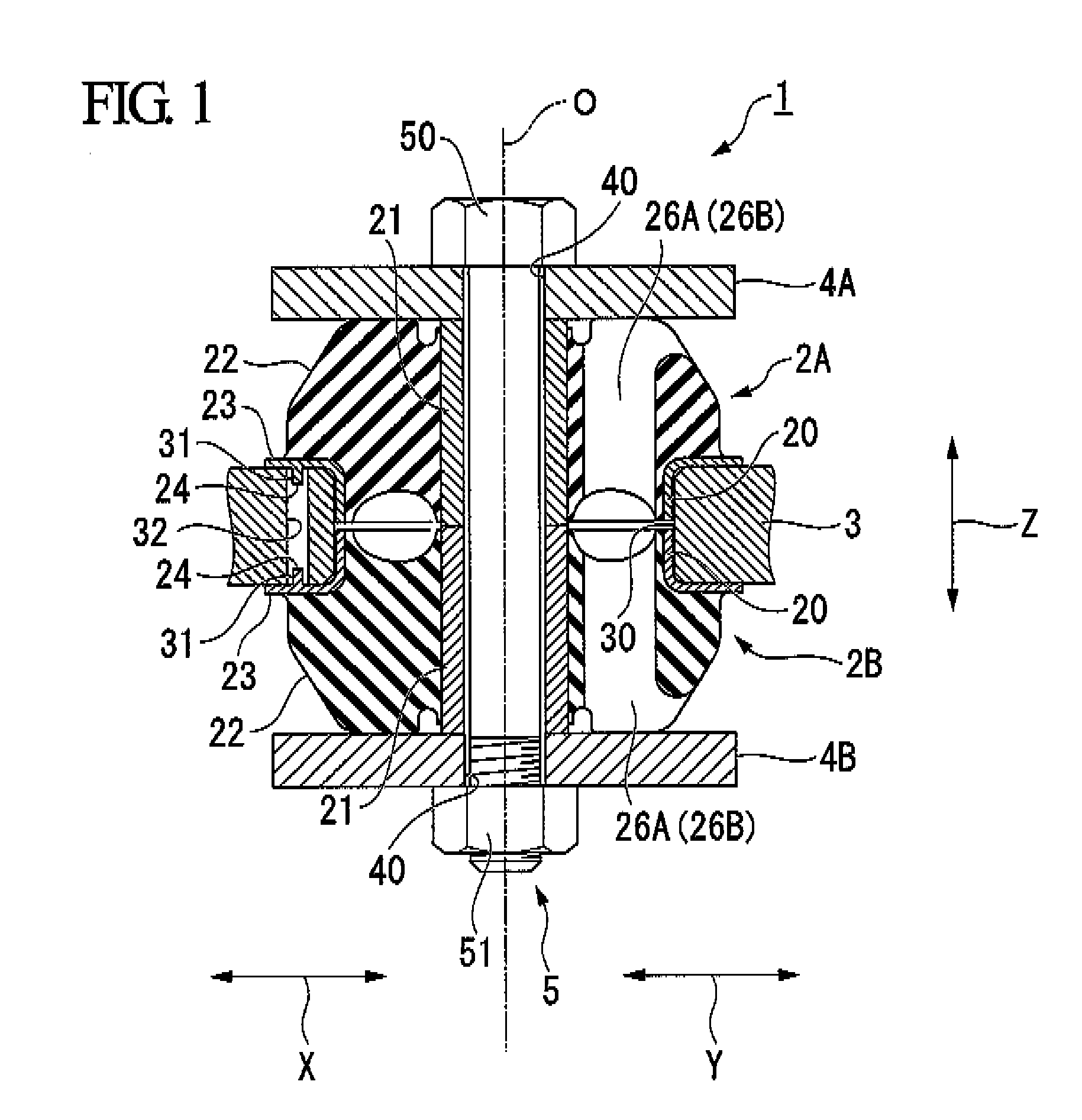
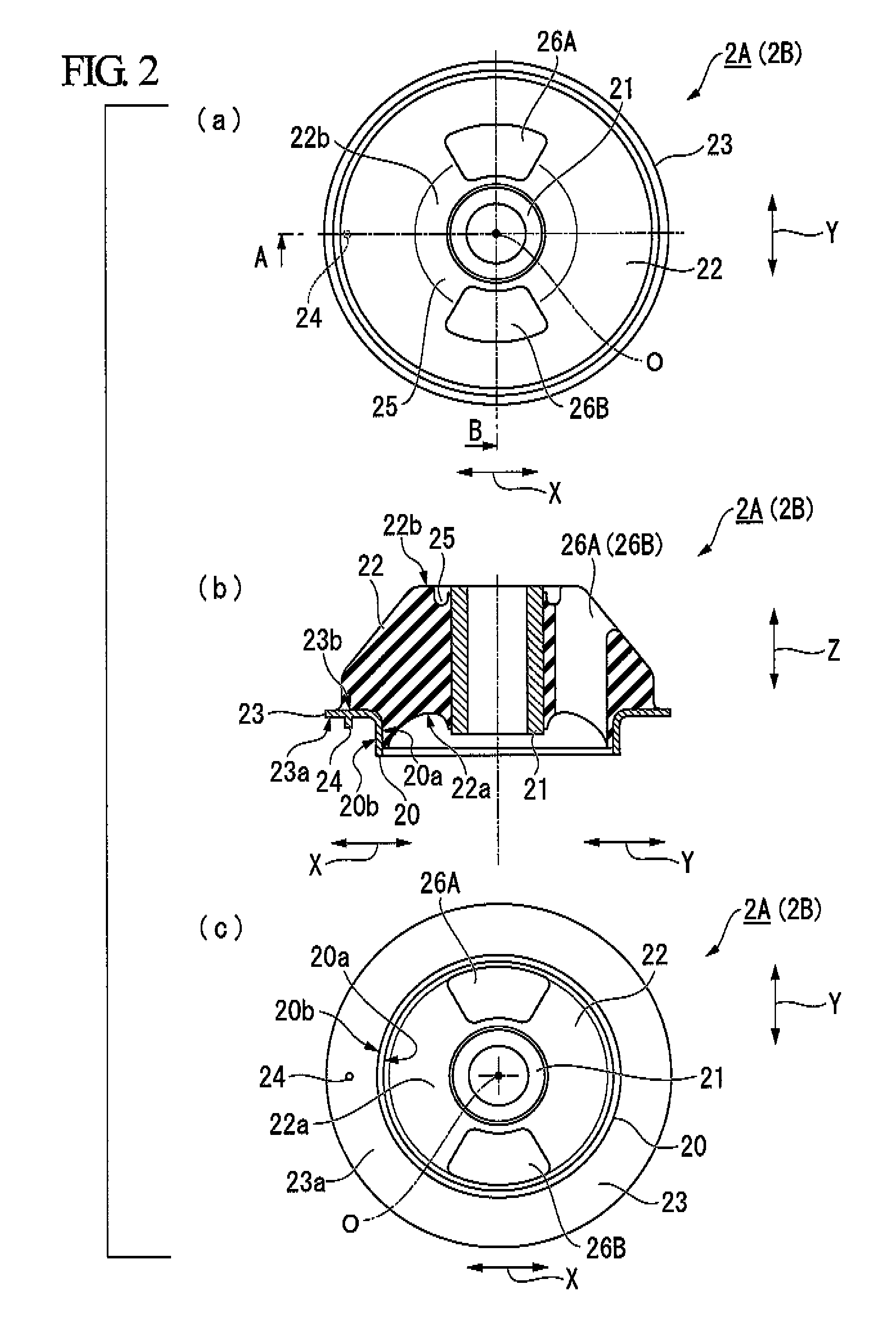
[0055]First of all, a vibration control equipment 1 according to the first embodiment will now be described with reference to FIGS. 1 to 3.
[0056]In the description below, the direction (horizontal direction) denoted by the symbol X shown in the figure is referred to as the front and rear direction, the direction (the vertical direction) denoted by the symbol Y shown in the figure is referred to as the left and right direction, and the direction (the vertical direction) denoted by the symbol Z shown in the figure is referred to as the upward and downward direction. Also, when viewing from one damping rubber 2A (2B), an opposite surface side (a lower side in (b) of FIG. 2) facing the other damping rubber 2B (2A) is referred to as an axial inner side, and a side (an upper side in (b) of FIG. 2) opposite to the surface is referred to as an axial outer side.
[0057]FIG. 1 is a cross-sectional view of a vibration control equipment 1 according to the first embodiment of the present invention...
second embodiment
[0092]Next, a vibration control equipment 101 according to a second embodiment of the present invention will now be described. Like parts are designated by the same reference numerals as the first embodiment, and the description thereof will be omitted herein.
[0093]FIG. 4 is a cross-sectional view of the vibration control equipment 101 according to the second embodiment.
[0094]FIG. 5 is a view showing an inner tube side segment body 110, in which (a) of FIG. 5 is a side view, (b) of FIG. 5 is a cross-sectional view, and (c) of FIG. 5 is a plan view when viewing at the axial inner side.
[0095]FIG. 6 is a view showing an outer tube side segment body 111, in which (a) of FIG. 6 is a plan view when viewing from the axial outer side, and (b) of FIG. 6 is a cross-sectional view.
[0096]The left half body (the left side of the central axis O) in FIG. 4, (b) of FIG. 5 and (b) of FIG. 6 is a cross-sectional view taken in the front and rear direction, while the right half body (the right side of ...
PUM
 Abstract
Description
Claims
Application Information
 - R&D
- Intellectual Property
- Life Sciences
- Materials
- Tech Scout
- Unparalleled Data Quality
- Higher Quality Content
- 60% Fewer Hallucinations
Browse by: Latest US Patents, China's latest patents, Technical Efficacy Thesaurus, Application Domain, Technology Topic, Popular Technical Reports.
© 2025 PatSnap. All rights reserved.Legal|Privacy policy|Modern Slavery Act Transparency Statement|Sitemap|About US| Contact US: help@patsnap.com


