Brushless motor

a brushless motor and motor body technology, applied in the direction of dynamo-electric machines, electrical equipment, supports/enclosements/casings, etc., can solve the problems of obstructing the improvement of brushless motor performance, difficult positioning of magnetic pole sensors and external stators, electrical insulation, etc., to prolong the permanent magnet and improve the positional accuracy of the two components

Active Publication Date: 2010-06-03
MITSUBISHI ELECTRIC CORP
View PDF18 Cites 29 Cited by
  • Summary
  • Abstract
  • Description
  • Claims
  • Application Information

AI Technical Summary

Benefits of technology

The present invention is a brushless motor that improves the accuracy of positioning the insulation plate and external stator. It also provides secure electrical insulation for the magnetic pole sensor and accurately detects the position of the permanent magnet's magnetic pole without prolonging it.

Problems solved by technology

The technical problem addressed by this patent is how to accurately detect the position of the magnetic pole in a brushless motor without adding extra components or increasing their size, while also securing optimal placement within the motor's structure. Additionally, the goal is to ensure proper insulation properties for the magnetic pole sensor.

Method used


Image

  • Brushless motor
  • Brushless motor
  • Brushless motor

Examples


first embodiment

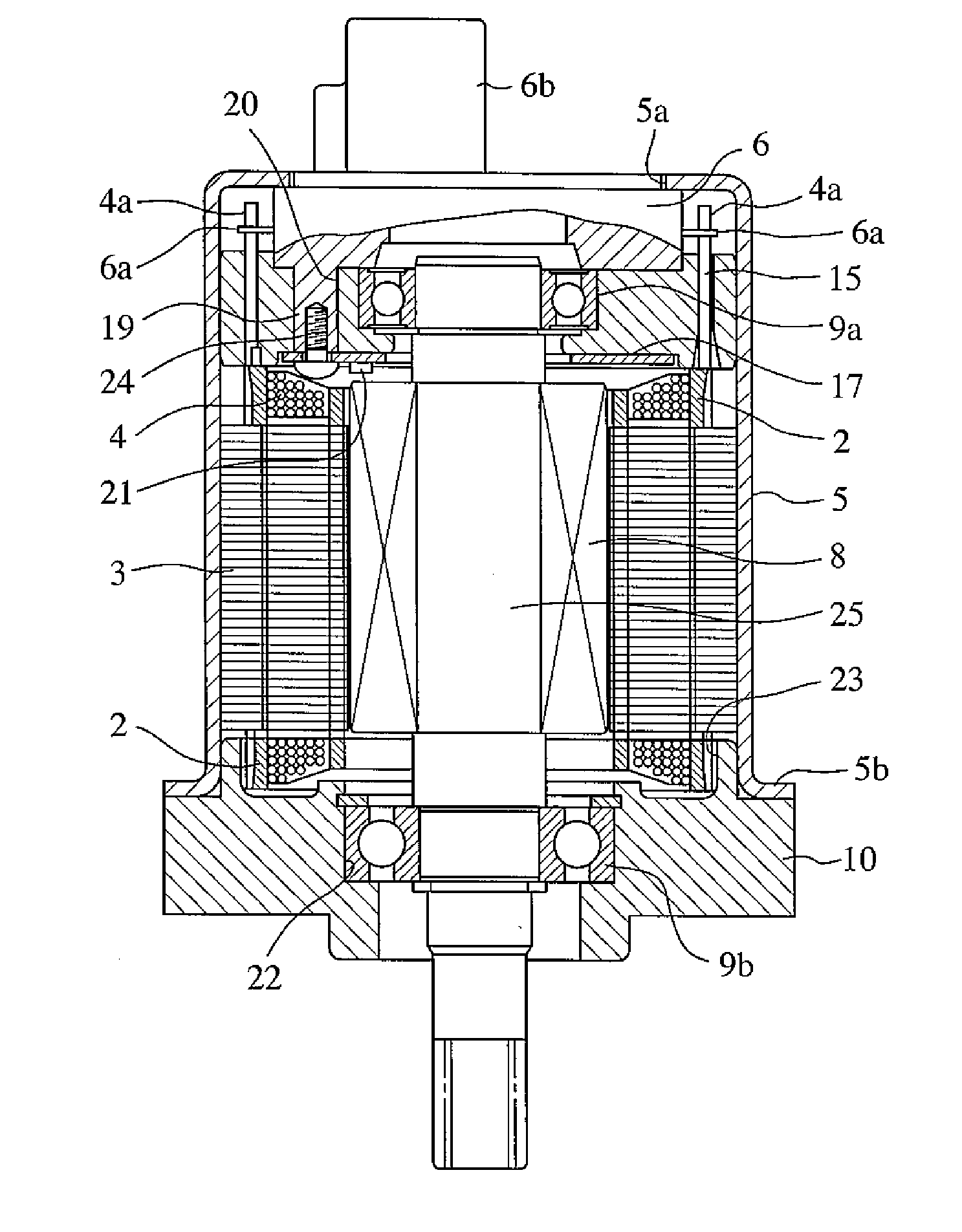
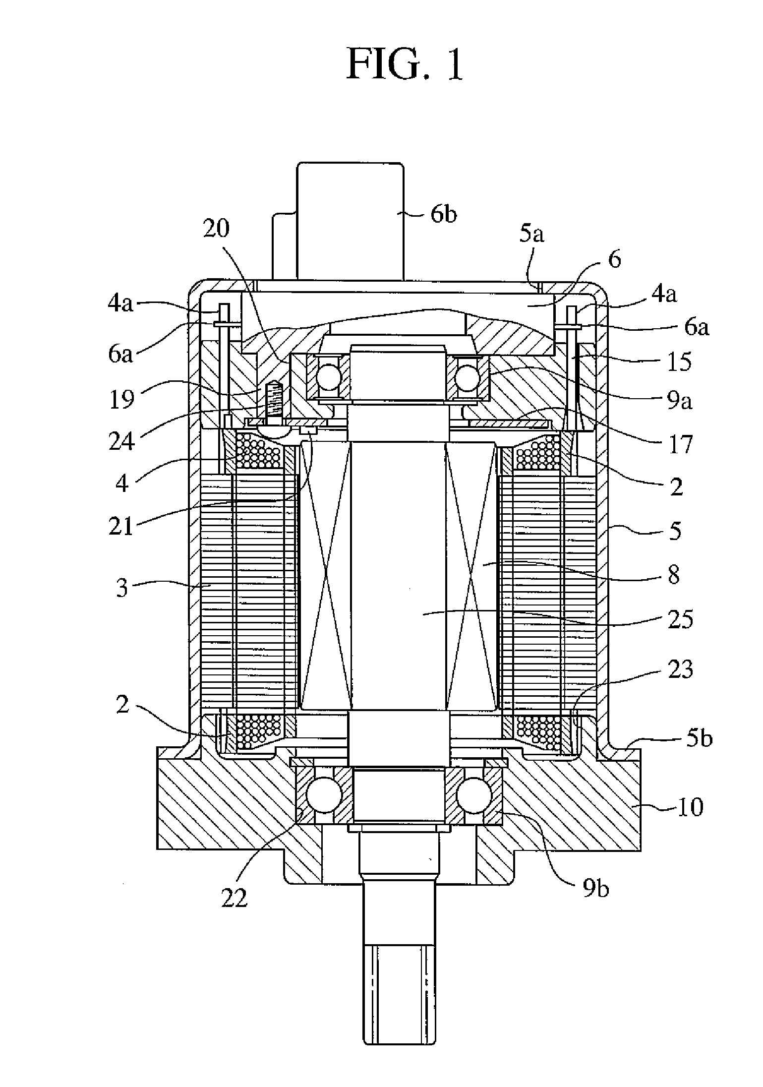
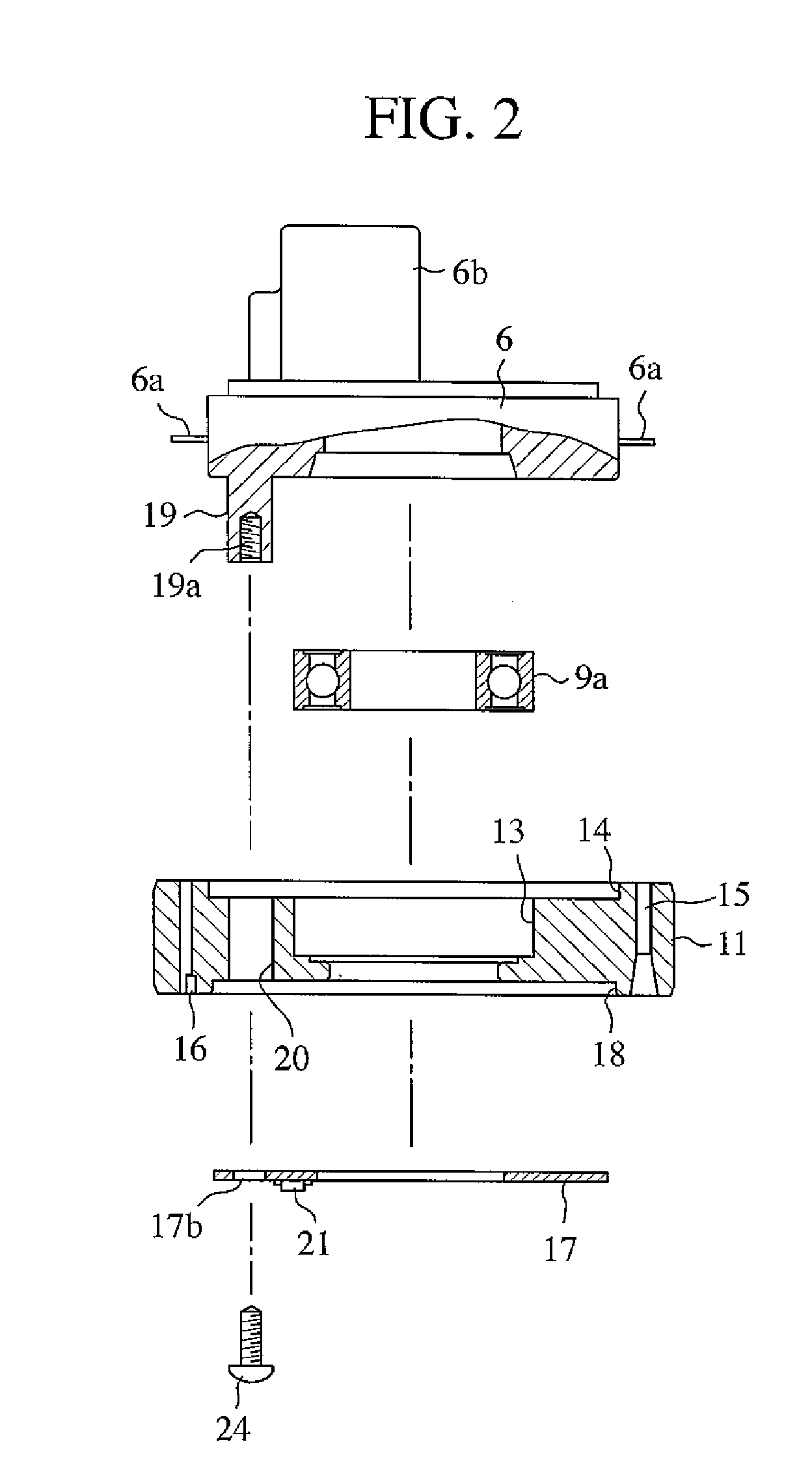
[0017]FIG. 1 is a longitudinal sectional view of a brushless motor according to the first embodiment of the present invention; FIG. 2 is an exploded perspective view of structural components attached to one end of an external stator; FIG. 3 is a longitudinal sectional view showing a relationship between the assembled body of the structural components shown in FIG. 2 and the external stator; FIG. 4 is a longitudinal sectional view showing a state where the assembled body of the structural components shown in FIG. 2 is assembled to the external stator; FIG. 5 is an enlarged view of a principal part, showing a relationship between a tip of electric wires passing a through hole of an insulation plate and a terminal of a bus bar; FIG. 6 is a longitudinal sectional view showing a relationship between the integrated component shown in FIG. 4 and an external case; and FIG. 7 is a longitudinal sectional view showing a relationship between the external stator and a housing to which an interna...


PUM


Abstract

A brushless motor includes an external stator where a magnetic circuit is electrically formed by winding electric wires around an iron core; a bus bar bundling the electric wires and forming an external input terminal; and an internal rotor formed by integrating a permanent magnet and rotatably supported through a bearing with respect to the external stator, wherein an insulation plate is held on one end of the external stator and attached thereto a magnetic pole sensor detecting a magnetic pole of the permanent magnet.

Description


Claims


Application Information

Patent Timeline
Owner MITSUBISHI ELECTRIC CORP
Why Eureka
Try Eureka