
Portable radar fairing

Inactive Publication Date: 2010-06-03
LOCKHEED MARTIN CORP
View PDF3 Cites 3 Cited by
  • Summary
  • Abstract
  • Description
  • Claims
  • Application Information

AI Technical Summary

Benefits of technology

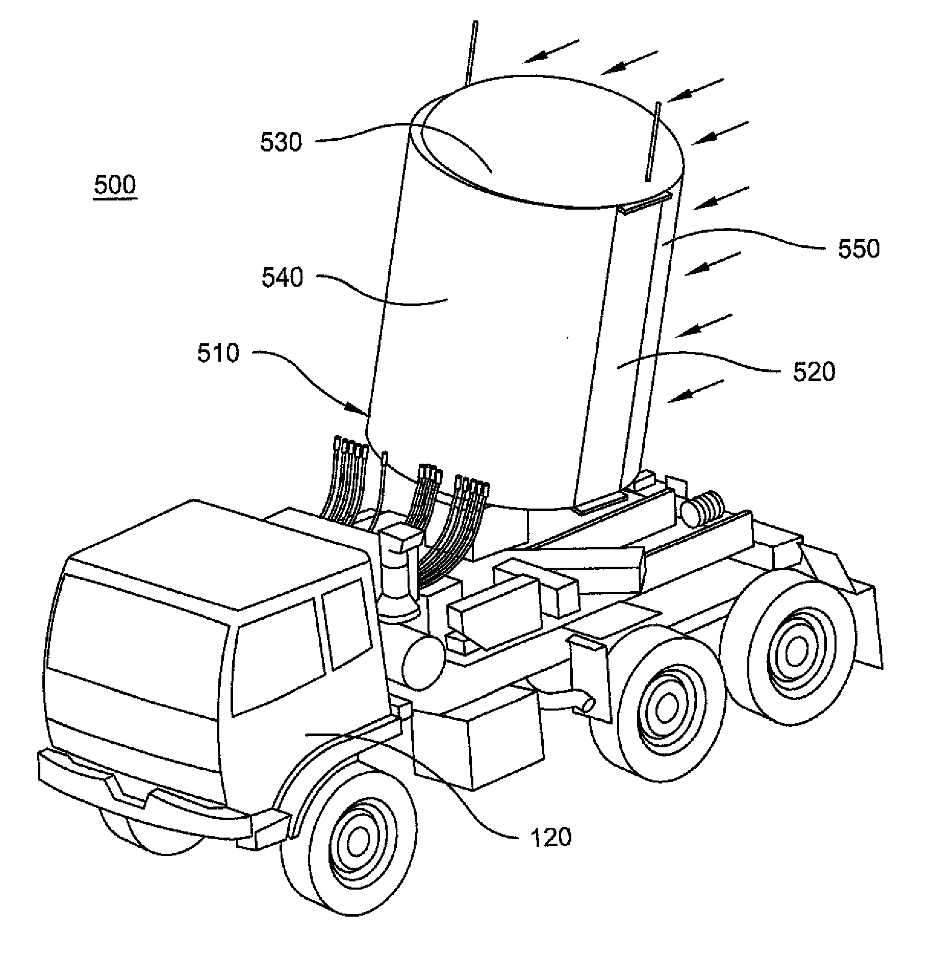
[0006]Yet another aspect of the invention includes a method of reducing drag forces on a radar array system. The method includes a step of providing at least partially open housing for the radar array, wherein the housing has curved sides. The method also includes a step of providing a curved covering mounted on the housing. The curved covering is adapted to cover the radar array. The curved covering and the housing form a generally curved structure.

Problems solved by technology

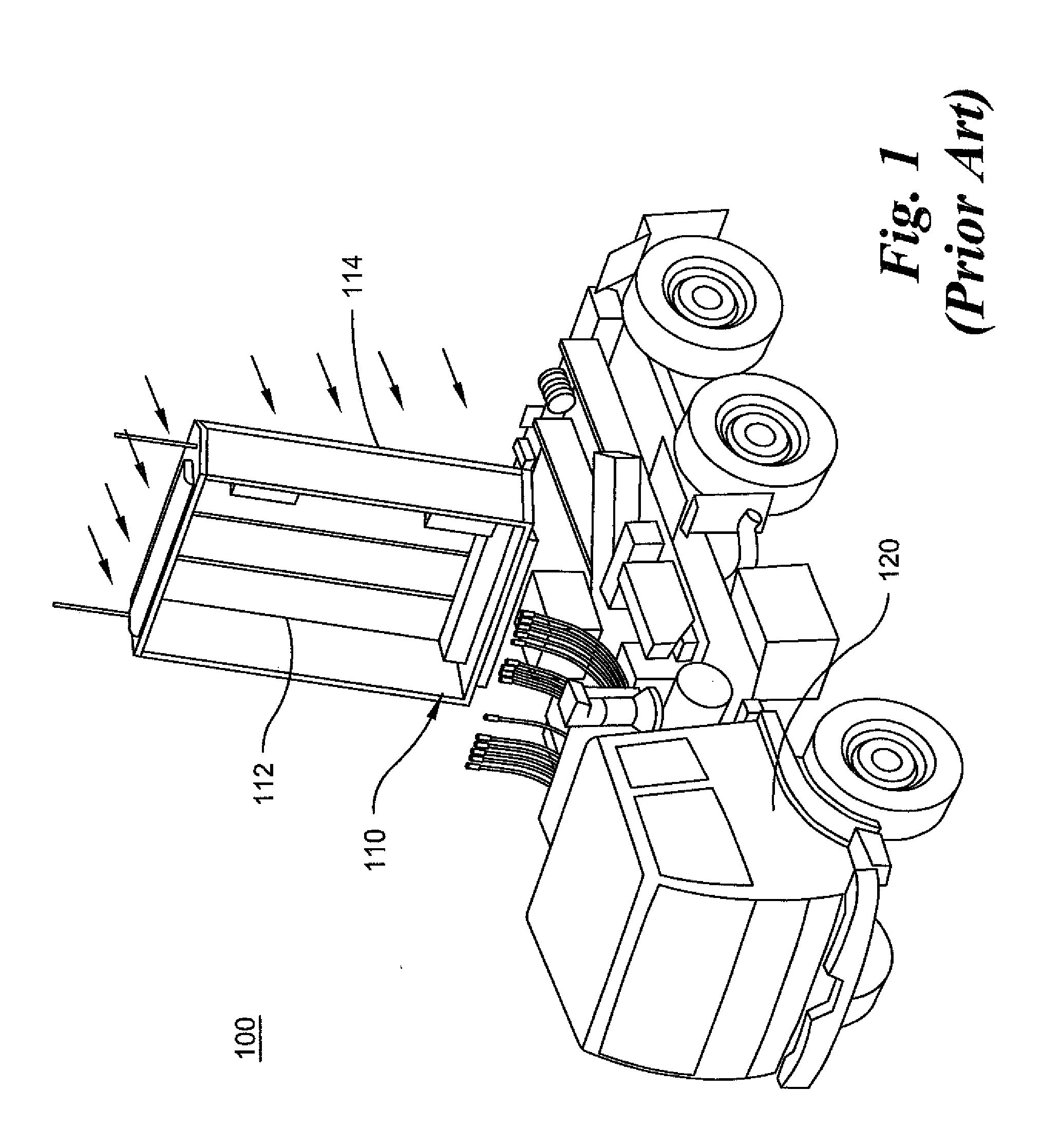
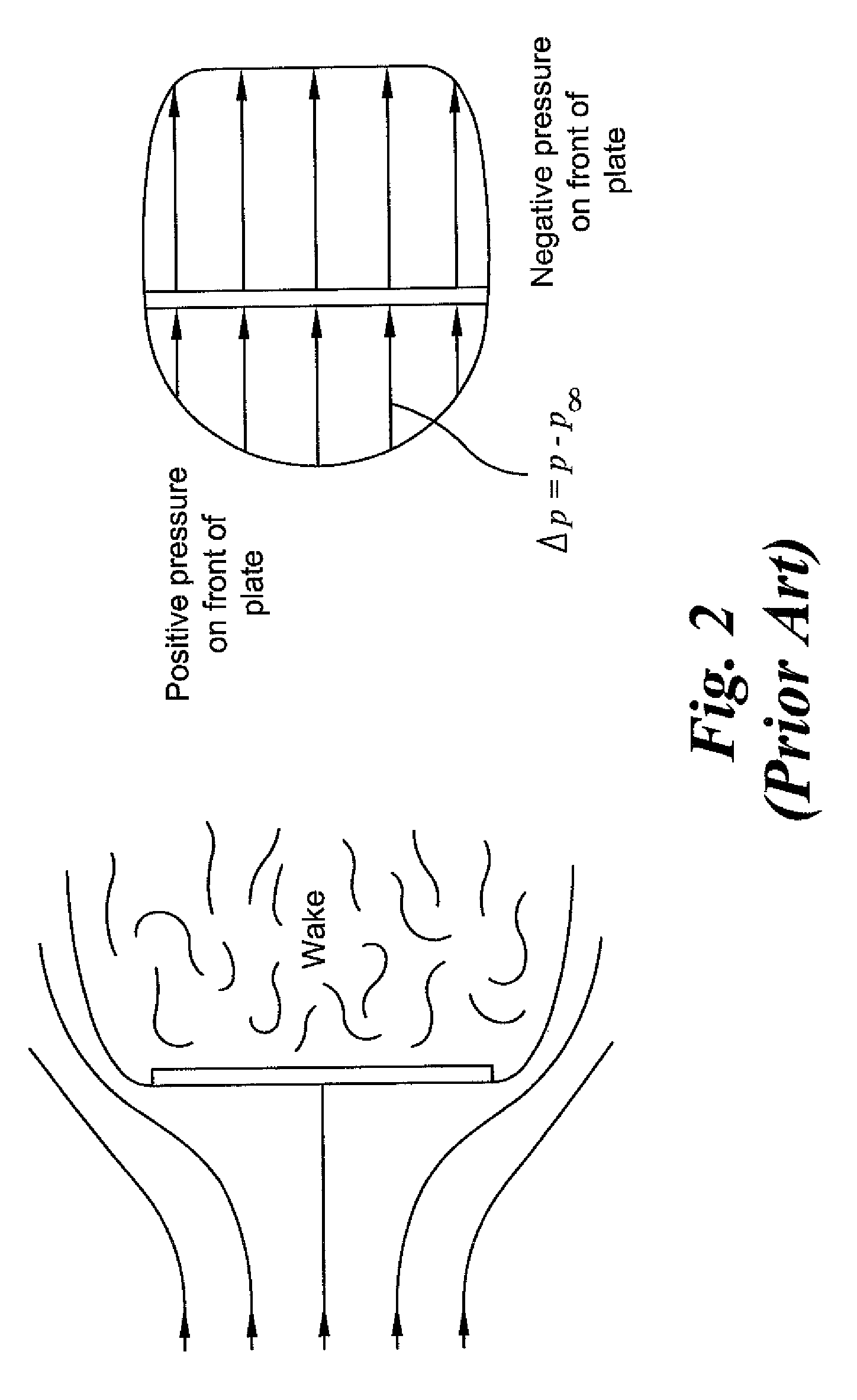
Such radar array designs result in high centers of gravity as well as large surface areas which are exposed to wind.
Frequently, mobile radar array systems are deployed on sloped terrain, where large and heavy bases are required for the stability of the radar arrays because of their high centers of gravity and large moment loads resulting from tall and planar designs.
Such methods, however, may either not be feasible or be too time-consuming and / or manpower intensive for mobile radar arrays, as mobile radar array systems generally require quick emplacement and displacement on the battlefield.

Method used


Image

  • Portable radar fairing
  • Portable radar fairing
  • Portable radar fairing

Examples


Embodiment Construction

[0019]The invention and its various embodiments can now be better understood by turning to the following detailed description of the exemplary embodiments which are presented as illustrated examples of the invention defined in the claims. It is expressly understood that the invention as defined by the claims may be broader than the illustrated embodiments described below. It is to be understood that the figures and descriptions of the present invention have been simplified to illustrate elements that are relevant for a clear understanding of the present invention, while eliminating, for purposes of clarity, many other elements found in mobile radar systems. However, because such elements are well known in the art, and because they do not facilitate a better understanding of the present invention, a discussion of such elements is not provided herein. The disclosure herein is directed to all such variations and modifications known to those skilled in the art. Although the following de...


PUM


Abstract

A portable fairing for a mobile radar array system includes at least partially open housing surrounding the mobile radar array and a curved covering mounted on the housing. The curved covering is adapted to cover the radar array in a closed position. The sides of the housing are curved such that when the curved covering is closed, the housing and the curved covering form a generally curved structure.

Description

FIELD OF THE INVENTION[0001]The invention relates generally to fairings, and more particularly to portable fairings for mobile radar array systems.BACKGROUND OF THE INVENTION[0002]Radar array systems, both permanent as well as mobile, generally have tall and planar designs for the array structure. Such radar array designs result in high centers of gravity as well as large surface areas which are exposed to wind. Frequently, mobile radar array systems are deployed on sloped terrain, where large and heavy bases are required for the stability of the radar arrays because of their high centers of gravity and large moment loads resulting from tall and planar designs. Moment loads are amplified significantly in strong, gusty winds. Mobile radar array systems are generally mounted on military vehicles for ease of movement and quick deployment in battlefields. Such military vehicles have to be fitted with heavy supporting mechanisms, for example, leveling outriggers and associated actuators,...

Claims


Application Information

Patent Timeline
IPC IPC(8): H01Q1/42
CPCH01Q1/1207
Inventor HALL, RICHARD R.HUTCHINSON, MATTHEW A.
Owner LOCKHEED MARTIN CORP
Learn More