Display unit, and displaying method for the binocular representation of a multicolor image

a display unit and multi-color technology, applied in the field of display units and displaying methods for the binocular representation of multi-color images, can solve the problem of impression of chromatic aberrations on the image for the right eye, and achieve the effect of reducing the chromatic aberration

Inactive Publication Date: 2010-06-03
CARL ZEISS SMT GMBH
View PDF11 Cites 170 Cited by
  • Summary
  • Abstract
  • Description
  • Claims
  • Application Information

AI Technical Summary

Benefits of technology

[0005]It is therefore an object of the invention to provide a display unit for binocular representation of a multicolor image which can be arranged in an extremely compact manner and simultaneously produces the lowest possible chromatic aberration.

Problems solved by technology

The disadvantageous aspect in the described unit is that as a result of the diffractive injection element and the diffractive extraction elements different chromatic aberrations are impressed on the image for the right eye and the left eye of the user.

Method used


Image

  • Display unit, and displaying method for the binocular representation of a multicolor image
  • Display unit, and displaying method for the binocular representation of a multicolor image
  • Display unit, and displaying method for the binocular representation of a multicolor image

Examples


Embodiment Construction

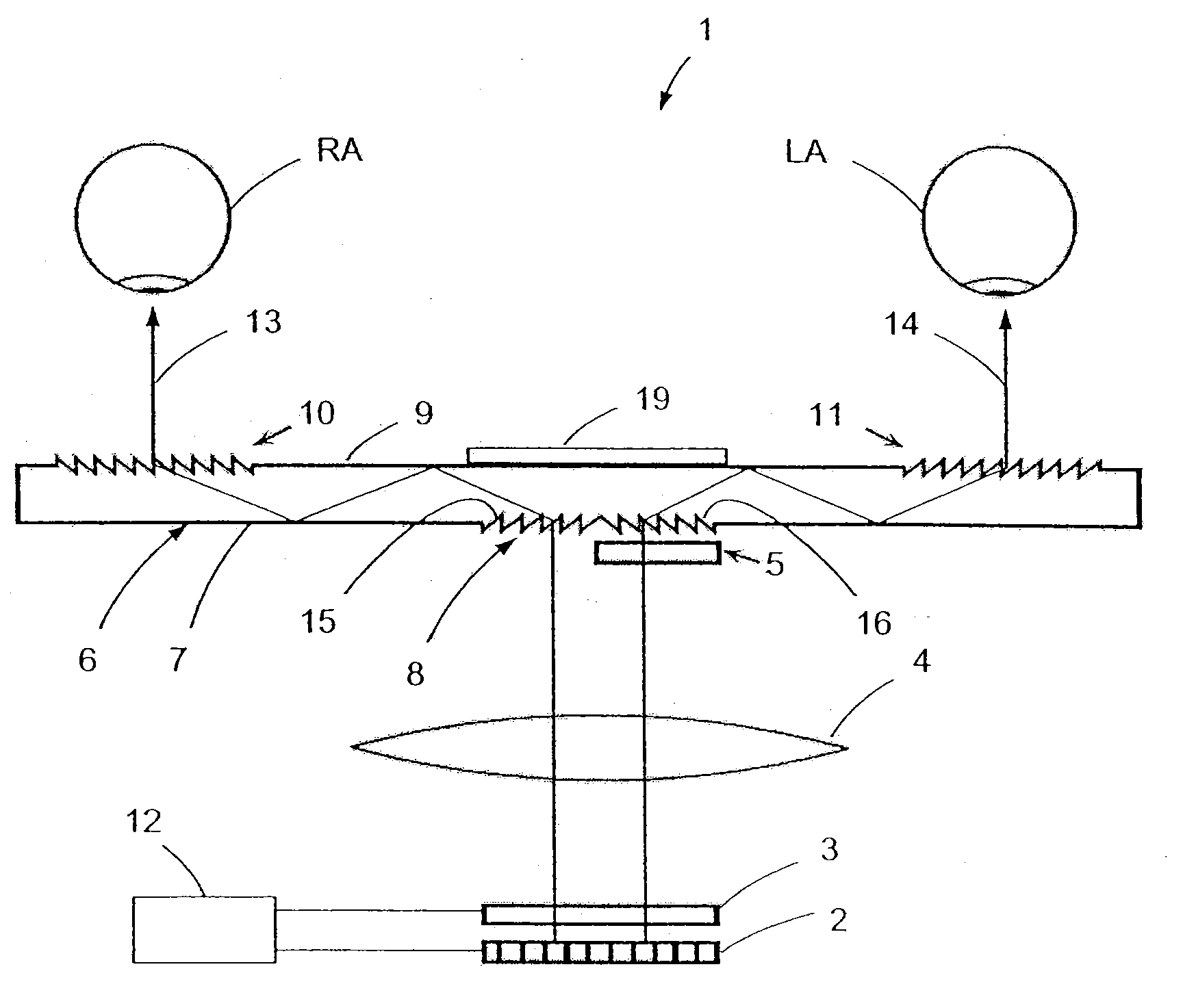
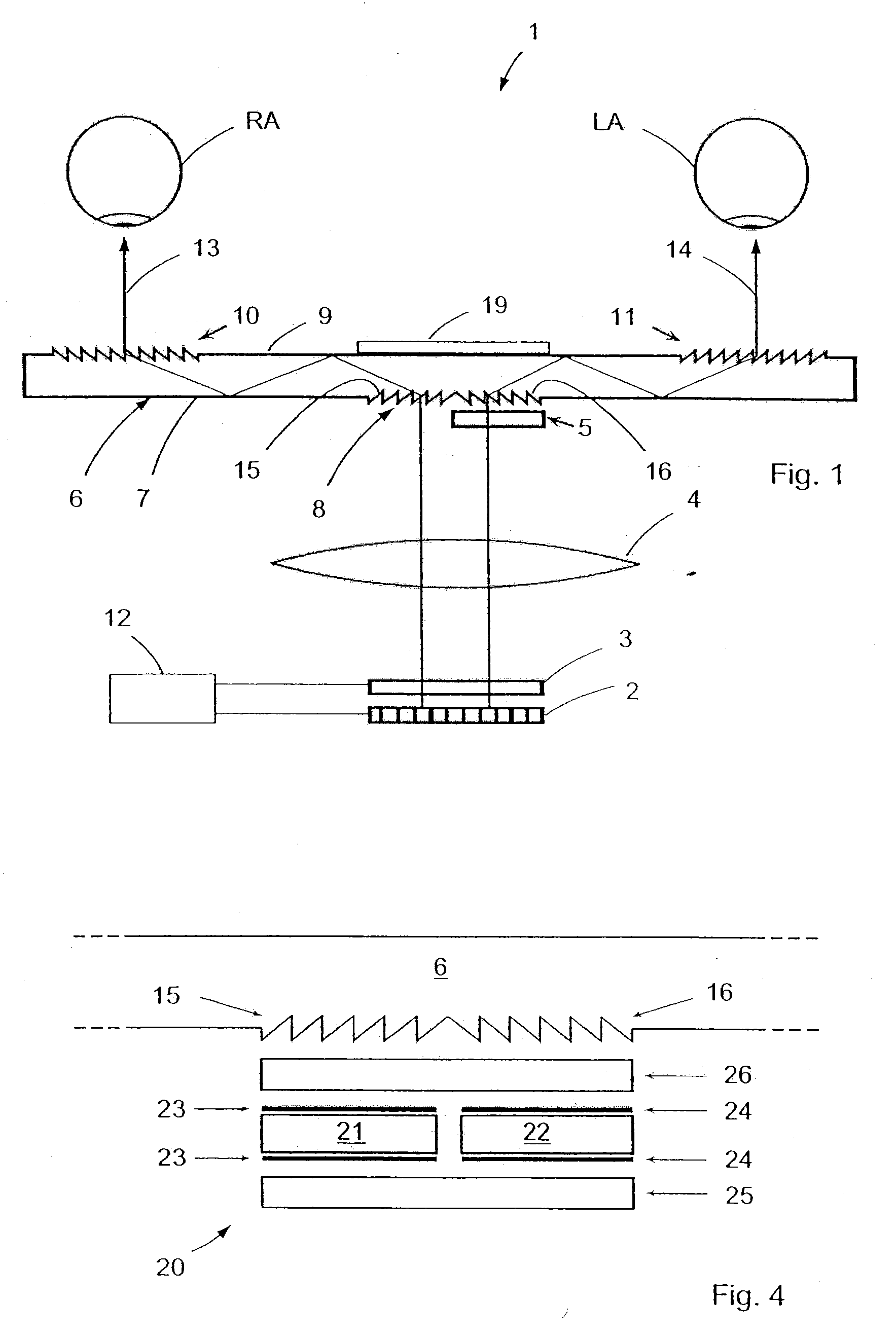
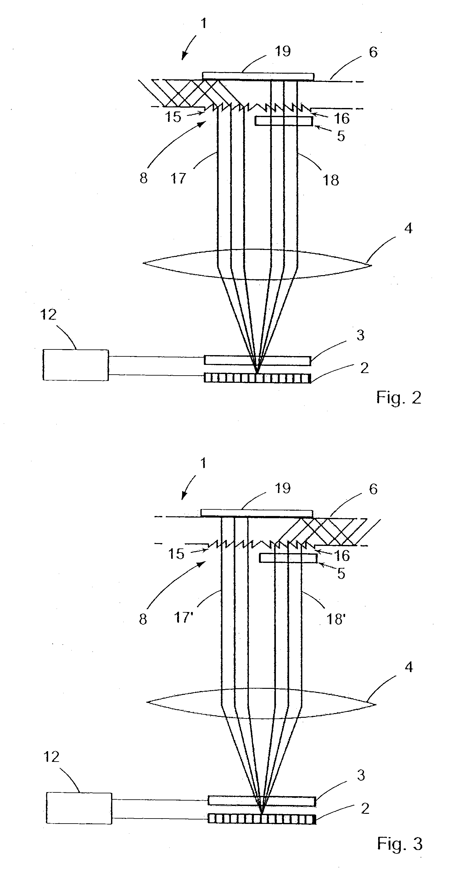
[0034]In the embodiment as shown in FIG. 1, the display unit 1 for binocular representation of a multicolor image comprises an imaging element 2, after which are located, in this sequence, a switchable polarization element which is arranged here as a liquid crystal element 3, a collimation lens 4, a λ / 2 plate 5 and a transparent planar plate 6. The planar plate 6 comprises a diffractive injection element 8 on its side 7 facing the imaging element 2 and two mutually spaced diffractive extraction elements 10, 11 on its side 9 opposed from the imaging element 2. The injection and extraction elements 8, 10 and 11 each always have the same groove spacing. Furthermore, a control unit 12 for triggering the imaging element 2 and the liquid crystal element is provided. It is understood that the sequence of the elements could also be different. For example, the collimation lens (4) and the liquid crystal element (3) could be exchanged with each other. The liquid crystal element can also be po...


PUM


Abstract

A display unit for binocular representation of a multicolor image including a control unit triggering an imaging element such that the imaging element generates in a temporal successive manner the image to be displayed for a first beam path and a second beam path as a first image and second image, respectively. The images are generated in a pre-distorted manner, opposite of the chromatic aberration of the respective beam path, such that the chromatic aberration generated in the respective beam path is compensated when the first and second image is displayed. The display unit includes a switching module which operates in temporal synchrony with the first and second image being generated, such that a user can see the first image only via the first beam path and the second image only via the second beam path.

Description

PRIORITY CLAIM[0001]The present application is a National Phase entry of PCT Application No. PCT / EP2008 / 001843, filed Mar. 7, 2008, which claims priority from German Application Number 102007021036.3, filed May 4, 2007, the disclosures of which are hereby incorporated by reference herein in their entirety.FIELD OF THE INVENTION[0002]The present invention relates to a display unit and a displaying method for the binocular representation of a multicolor image. Such a unit is frequently arranged as an HMD apparatus (head-mounted-display apparatus) which should be as small and compact as possible.BACKGROUND[0003]Such a unit with a single imaging element and a transparent substrate arranged as a plane-parallel plate with a diffractive injection element and a first and second diffractive extraction element which are arranged at a distance from one another is described in T. Levola: “Diffractive optics for virtual reality displays”, Journal of the SID 14 / 5 (2006), pages 467 through 475. Th...

Claims


Application Information

Patent Timeline
Patent Type & Authority Applications(United States)
IPC IPC(8): G09G5/10G09G5/00
CPCG02B5/30G02B6/0038G02B27/2264G02B27/0081G02B27/0172G02B6/0076G02B30/24G02B6/0058G02B6/0075
Inventor SEESSELBERG, MARKUSRUOFF, JOHANNES
Owner CARL ZEISS SMT GMBH
Why Eureka
Try Eureka