Visible light communication apparatus and visible light communciation method

a communication apparatus and visible light technology, applied in electrical apparatus, electromagnetic transmission, close-range type systems, etc., can solve the problems of difficult to achieve synchronization of transmitting data in a pwm signal section, difficult to combine the modulation signal for communication with the control signal, and the luminance of illumination cannot emit the desired luminance. achieve the effect of preventing the function of luminance control of illumination

Active Publication Date: 2010-06-03
ELECTRONICS & TELECOMM RES INST
View PDF11 Cites 56 Cited by
  • Summary
  • Abstract
  • Description
  • Claims
  • Application Information

AI Technical Summary

Benefits of technology

[0015]The present invention proposes to solve the problems in the related art. It is an object of the present invention to provide an apparatus and method capable of performing visible light communication without hindering a luminance control function of illumination in an illumination device using an LED.

Problems solved by technology

However, the illumination device that controls luminance using the PWM scheme is difficult to use the visible light communication and the luminance of illumination cannot emit the desired luminance due to the visible wireless communication function.
However, It is difficult to combine the PWM signal for controlling luminance and the modulation signal for communication with the control signal for turning-on / off the LED.
In other words, it is difficult to achieve synchronization for transmitting data in a PWM signal section.
This means that the luminance of the LED illumination is changed according to the data pattern as well as the transmission data cannot be transmitted as it is.
In this case, however, the turn on time of illumination is substantially short, such that the desired luminance cannot be shown.

Method used


Image

  • Visible light communication apparatus and visible light communciation method
  • Visible light communication apparatus and visible light communciation method
  • Visible light communication apparatus and visible light communciation method

Examples


Embodiment Construction

[0040]Hereinafter, a visible light communication apparatus and method according to an embodiment of the present invention will be described with reference to the accompanying drawings.

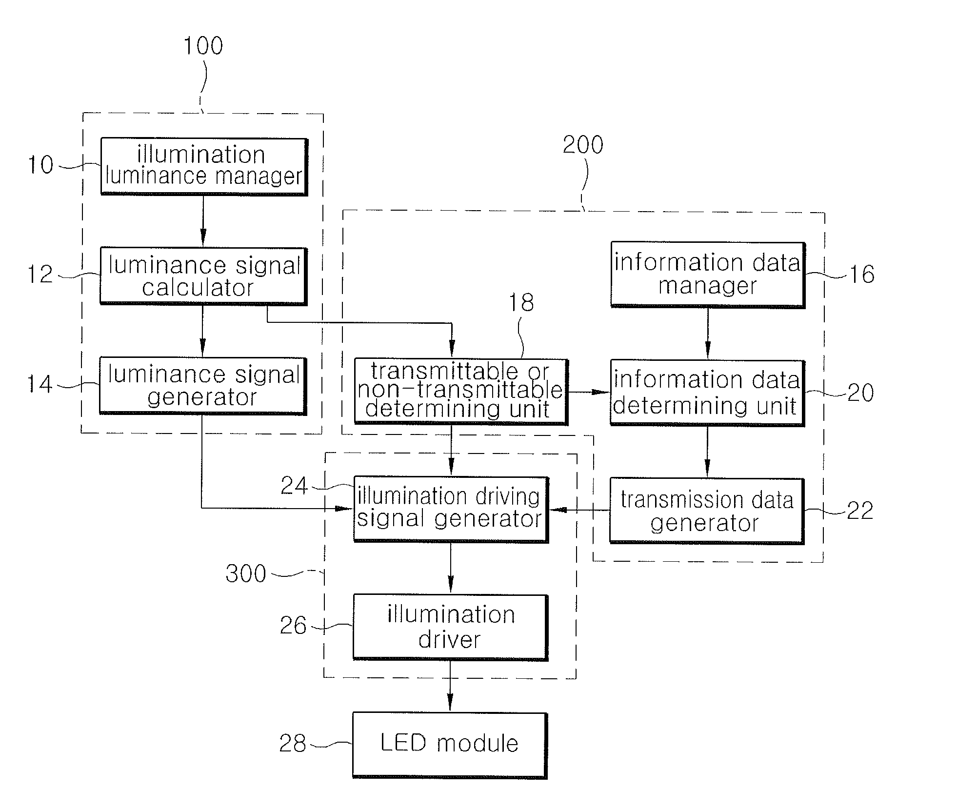
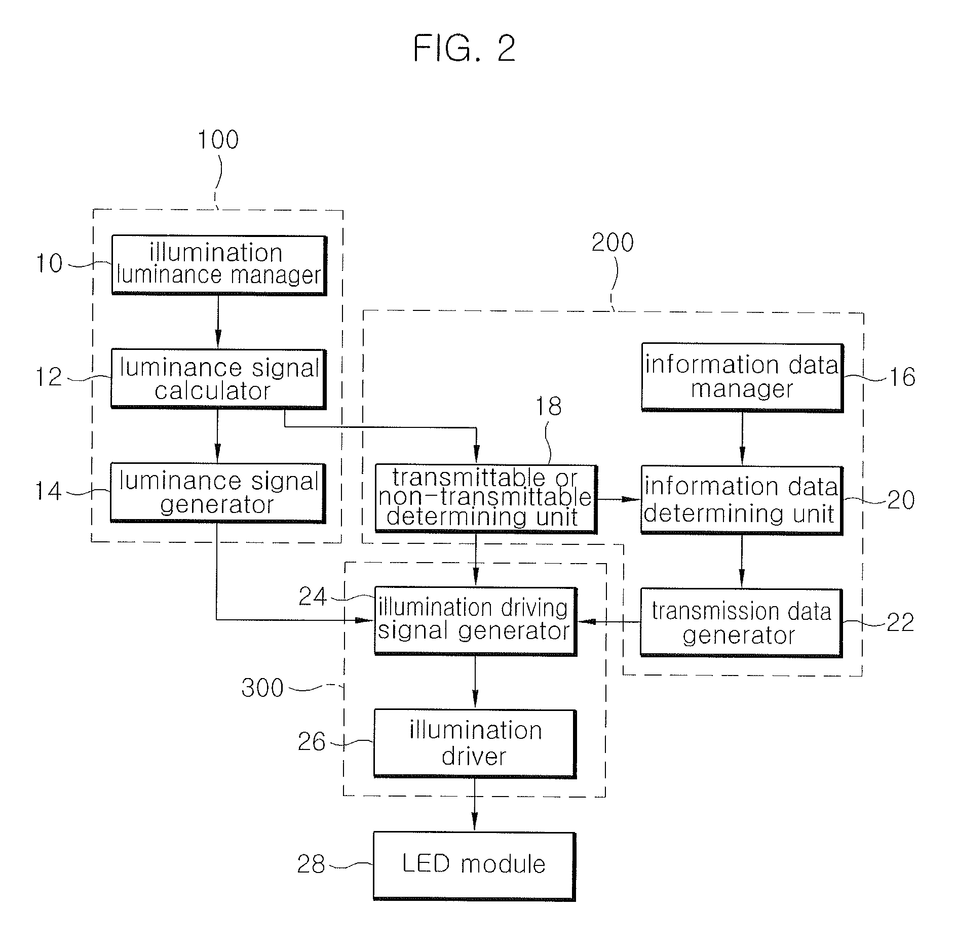
[0041]FIG. 2 is a block configuration diagram of a visible light communication apparatus according to an embodiment of the present invention.

[0042]An embodiment of the present invention includes an illumination luminance manager 10, a luminance signal calculator 12, a luminance signal generator 14, an information data manager 16, a transmittable or non-transmittable determining unit 18, an information data determining unit 20, a transmission data generator 22, an illumination driving signal generator 24, an illumination driver 26, and LED module 28.

[0043]The illumination luminance manager 10 analyzes a luminance request information input in various forms, converts it into the corresponding digital information, and then outputs it. The luminance request information is input in an analog or digital schem...


PUM


Abstract

The visible light communication apparatus includes: a luminance signal generator that calculates a duty cycle of an illumination driving signal corresponding to input luminance request information and generates clock frequency information on luminance signals based on the calculated duty cycle; a transmission data generator that generates transmission data; an illumination driver that generates and outputs an illumination driving signal in a pulse waveform based on the clock frequency information of the luminance signals and the transmission data and controls a pulse position of a turn on section for each bit unit time in the waveform of the illumination driving signal based on the transmission data; and an illumination that is operated according to the illumination driving signal from the illumination driver.

Description

RELATED APPLICATIONS[0001]The present application claims priority to Korean Patent Application Serial Number 10-2008-0119698, filed on Nov. 28, 2008, the entirety of which is hereby incorporated by reference.BACKGROUND OF THE INVENTION[0002]1. Field of the Invention[0003]The present invention relates to a visible light communication apparatus and a visible light communication method, and more specifically, to an apparatus and method capable of performing visible wireless communication while controlling the luminance of LED illumination.[0004]2. Description of the Related Art[0005]Currently, the number of wired telephone subscribers, mobile communication subscribers, and Internet users are almost at saturated state, thus, there is a need to find new technologies by converging industries under the situation where the increase in the number of the subscribers stops. Due to the above situation, a new illumination industry in which an LED technology in 2007 had rapidly developed, includi...

Claims


Application Information

Patent Timeline
Patent Type & Authority Applications(United States)
IPC IPC(8): H04B10/00
CPCH04B10/116H04B10/1141
Inventor KIM, DAEHOKANG, TAEGYULIM, SANGKYUKIM, TAEWANCHUNG, MYUNGAESOHN, SUNGWON
Owner ELECTRONICS & TELECOMM RES INST
Why Eureka
Try Eureka