Apparatus and method for manipulating a component of a wind turbine

a technology for wind turbines and components, applied in the direction of wind turbines, wind motors with parallel air flow, liquid fuel engine components, etc., can solve the problem that wind generators require maintenan

Inactive Publication Date: 2010-06-03
GENERAL ELECTRIC CO
View PDF11 Cites 58 Cited by
  • Summary
  • Abstract
  • Description
  • Claims
  • Application Information

AI Technical Summary

Problems solved by technology

Over time, the wind generators require maintenance.
Debris, birds and the like oftentimes impact the blades and cause damage.

Method used


Image

  • Apparatus and method for manipulating a component of a wind turbine
  • Apparatus and method for manipulating a component of a wind turbine
  • Apparatus and method for manipulating a component of a wind turbine

Examples


Embodiment Construction

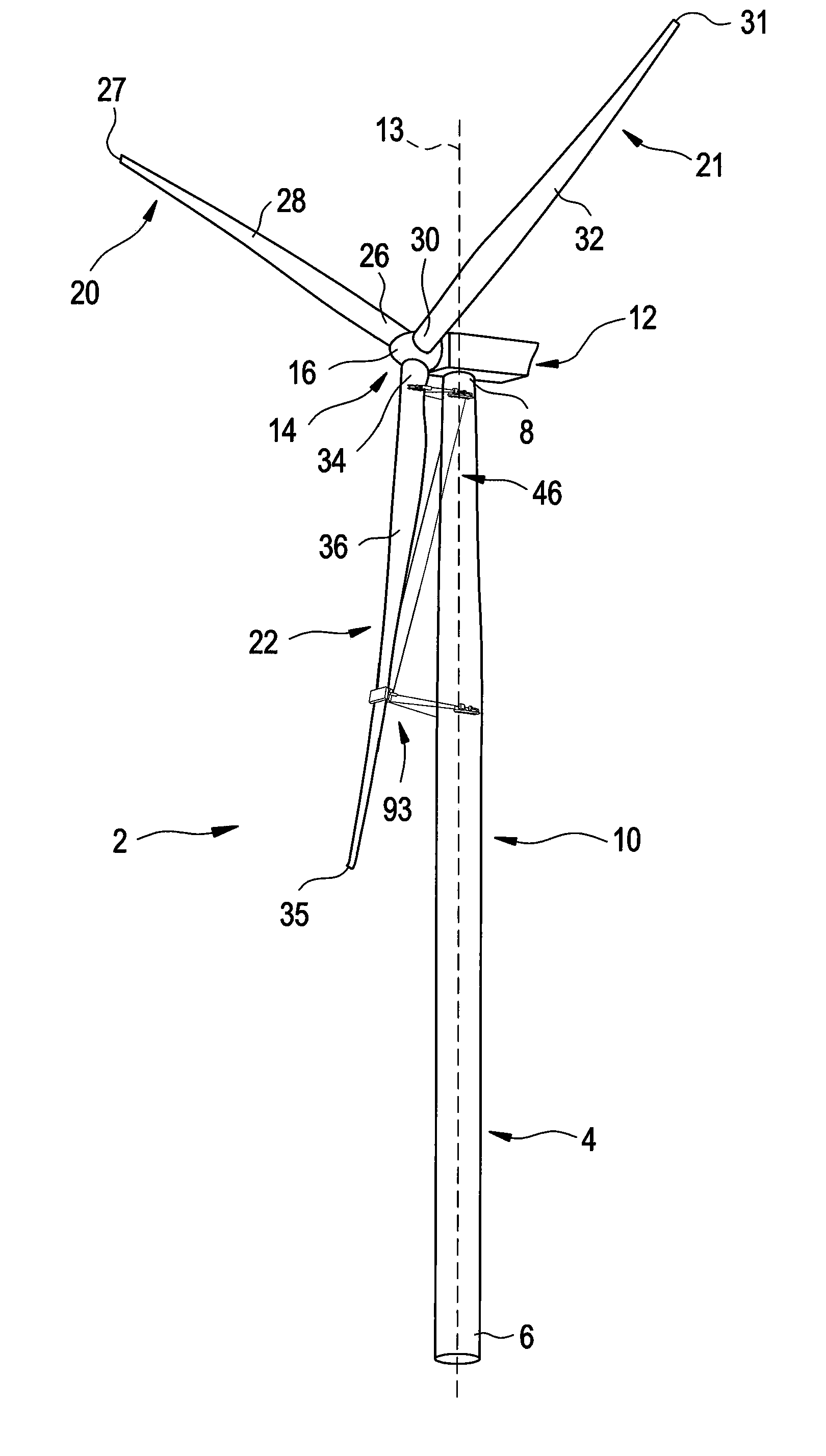
[0017]With reference to FIG. 1, a wind turbine constructed in accordance with an exemplary embodiment is indicated generally at 2. Wind turbine 2 can be readily supported upon land or, at sea in order to capture wind currents that are converted into electrical power. Towards that end, wind turbine 2 includes a tower member 4 having a first end portion 6 that extends to a second end portion 8 through an intermediate portion 10. Wind turbine 2 further includes a yaw system / nacelle 12 that is positioned at a second end portion 8 of tower member 4. As will be discussed more fully below, yaw system 12 rotates about an axis 13 defined by tower member 4. Wind turbine 2 is further shown to include a wind energy collection system 14 operatively coupled to yaw system 12. Wind energy collection system 14 includes a central hub 16 having attached thereto a plurality of blade members 20-22. Blade members 20-22 collectively rotate in response to wind currents. Blade members 20-22 are also individ...


PUM

PropertyMeasurementUnit
energyaaaaaaaaaa
electrical currentaaaaaaaaaa
rate of rotationaaaaaaaaaa

Abstract

A wind turbine includes a tower member a yaw system, and a wind energy collection system. The wind energy collection system includes a central hub and a plurality of blade members. The wind turbine further includes a component manipulating system operatively coupled between at least one of the plurality of blade members and the tower member. The component manipulating system includes a blade member support structure including a first end pivotally connected relative to the tower member that extends to a second end operatively coupled to the one of the plurality of blade members, and a winching system operatively connected to the one of the plurality of blade members and the tower member. The winching system is selectively operated to shift the one of the plurality of blade members relative to the tower member in order to enable serving of the wind turbine.

Description

BACKGROUND OF THE INVENTION[0001]The subject matter disclosed herein relates to wind turbines and, more particularly, to an apparatus and method for servicing a component of a wind turbine.[0002]Alternative sources of energy are under development in order to meet the world's power demand. One such alternative energy source is wind power. Wind generators convert energy provided by air currents into electricity. The air currents rotate large rotor blades or propellers that are mounted in nacelles at the top of a tower. The blades spin a rotor relative to a stator to generate an electrical current. The rate of rotation is controlled by varying blade pitch as well as through the use of various braking systems. During high wind conditions, the blade pitch is adjusted to spill wind energy in order to limit rotational speed. Occasionally, the braking system is employed to further prevent the blades from achieving high rotational speeds. During low wind conditions, the blade pitch is adjust...

Claims


Application Information

Patent Timeline
Patent Type & Authority Applications(United States)
IPC IPC(8): F03D7/02F03D11/00B23P11/00
CPCF03D1/003F05B2230/61Y10T29/49318Y02E10/722Y10S416/06Y02E10/721F03D80/50Y02E10/72Y02P70/50F05B2230/80
Inventor NIES, JACOB JOHANNES
Owner GENERAL ELECTRIC CO
Why Eureka
Try Eureka