Vane structure for vertical axis wind power generator

a technology of wind power generator and vertical axis, which is applied in the direction of machines/engines, renewable energy generation, greenhouse gas reduction, etc., can solve the problems of disadvantageous reduction of wind power generation accordingly, and achieve the effect of effectively intercepting wind power, effective utilization of wind power, and increasing air resistan

Inactive Publication Date: 2010-06-03
YEH DONG HUA
View PDF5 Cites 13 Cited by
  • Summary
  • Abstract
  • Description
  • Claims
  • Application Information

AI Technical Summary

Benefits of technology

[0019]To achieve the above and other objects, the vane structure for vertical axis wind power generator according to another preferred embodiment of the present invention includes a plurality of vanes mounted around and spaced along a main shaft of the wind power generator. Each of the vanes includes a vane body, a first arcuate guide bar, an openwork screen, a first movable baffle unit, and a second movable baffle unit. The vane body has a body portion that defines a rearward recess and includes a front plate portion, on which a through hole is formed. The first arcuate guide bar is located in the rearward recess, and has a first end and an opposing second end. The second end is fixedly connected to the body portion and the first end is located at a center of the through hole. The openwork screen is fitted in the through hole and connected to the first end of the first arcuate guide bar. The first movable baffle unit has openings formed thereon and is located in the rearward recess of the vane body behind the openwork screen. The first movable baffle unit includes a second arcuate guide bar in the form of a sleeve slidably fitted around the first arcuate guide bar, and is connected to the front plate portion of the vane body via a pivot point on a baffle support bar, so that the first movable baffle unit is turnable about the pivot point to openably cover the openwork screen from one side adjacent to the rearward recess. The second arcuate guide bar has a proximal end and a distal end, and a radially outward extended flange formed around the distal end. The second movable baffle unit is located in the rearward recess of the vane body behind the first movable baffle unit, and is slidably fitted around the second arcuate guide bar to openably cover the first movable baffle unit from one side adjacent to the rearward recess. When the rearward recess of the vane body is located against the wind, the first and the second movable baffle unit on the vane body are located at a closed position to cover the openwork screen and the through hole, allowing the rearward recess to effectively intercept the wind force; and when the rearward recess of the vane body is located before the wind, the first and the second movable baffle unit are naturally opened, allowing the wind to quickly move through the through hole to outer sides of the vane body without producing an increased air resistance to the rotating vane body. That is, the vane with the rearward recess located against the wind can effectively utilize the wind force without being adversely affected by an opposing vane that has the rearward recess located before the wind at the same time. Thus, the main shaft of the wind power generator can be more easily driven by the vanes to rotate.
[0020]Preferably, a second buffer spring is provided between the first and the second movable baffle unit to buffer the impact therebetween, so as to avoid damaged parts and noise caused by such impact.

Problems solved by technology

Since the wind force capable of driving the main shaft to rotate is reduced, the effect of wind power generation is disadvantageously reduced accordingly.

Method used


Image

  • Vane structure for vertical axis wind power generator
  • Vane structure for vertical axis wind power generator
  • Vane structure for vertical axis wind power generator

Examples


Embodiment Construction

[0030]The present invention will now be described with two preferred embodiments thereof. For the purpose of easy to understand, elements that are the same in the two preferred embodiments are denoted by the same reference numerals.

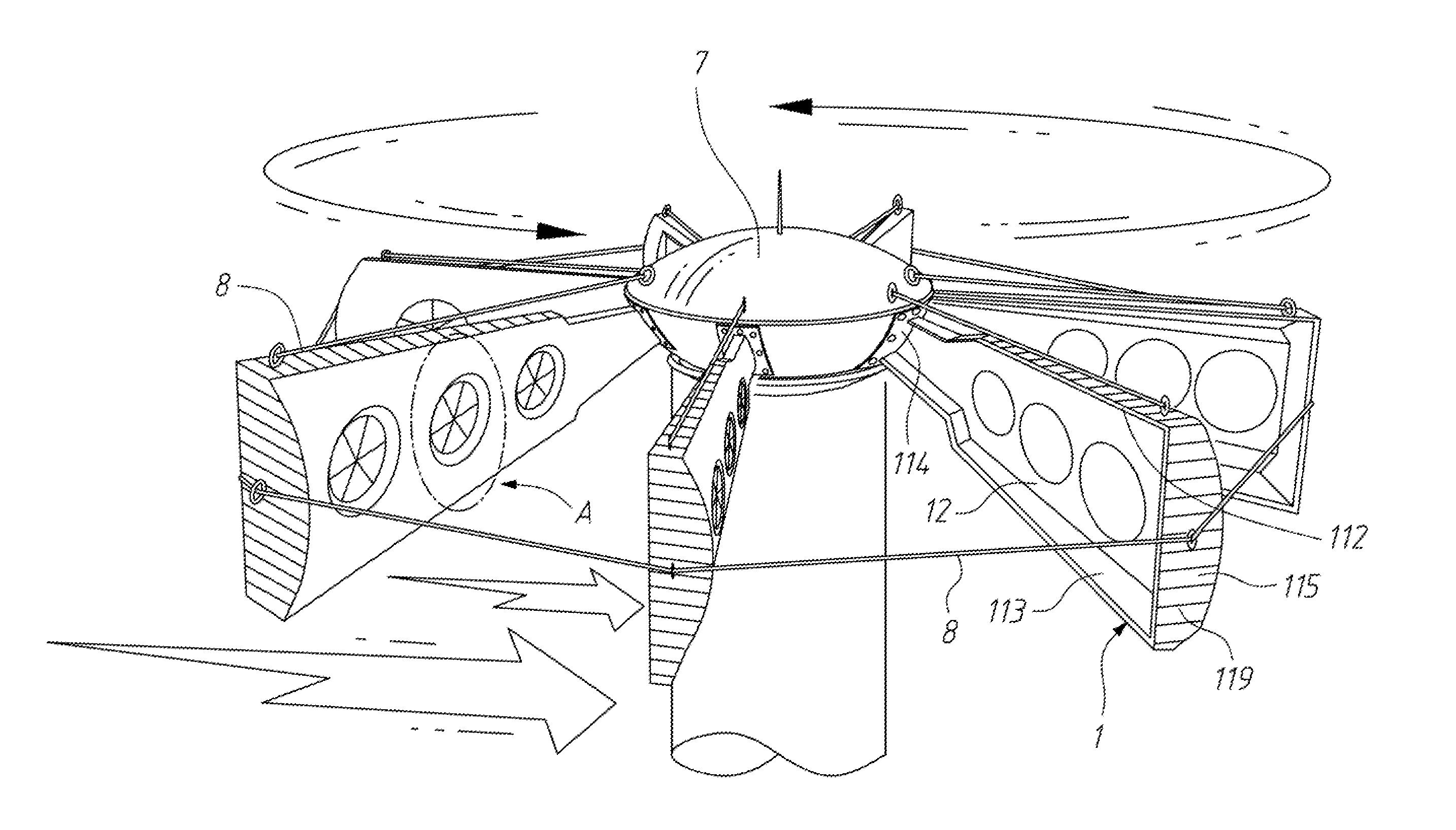
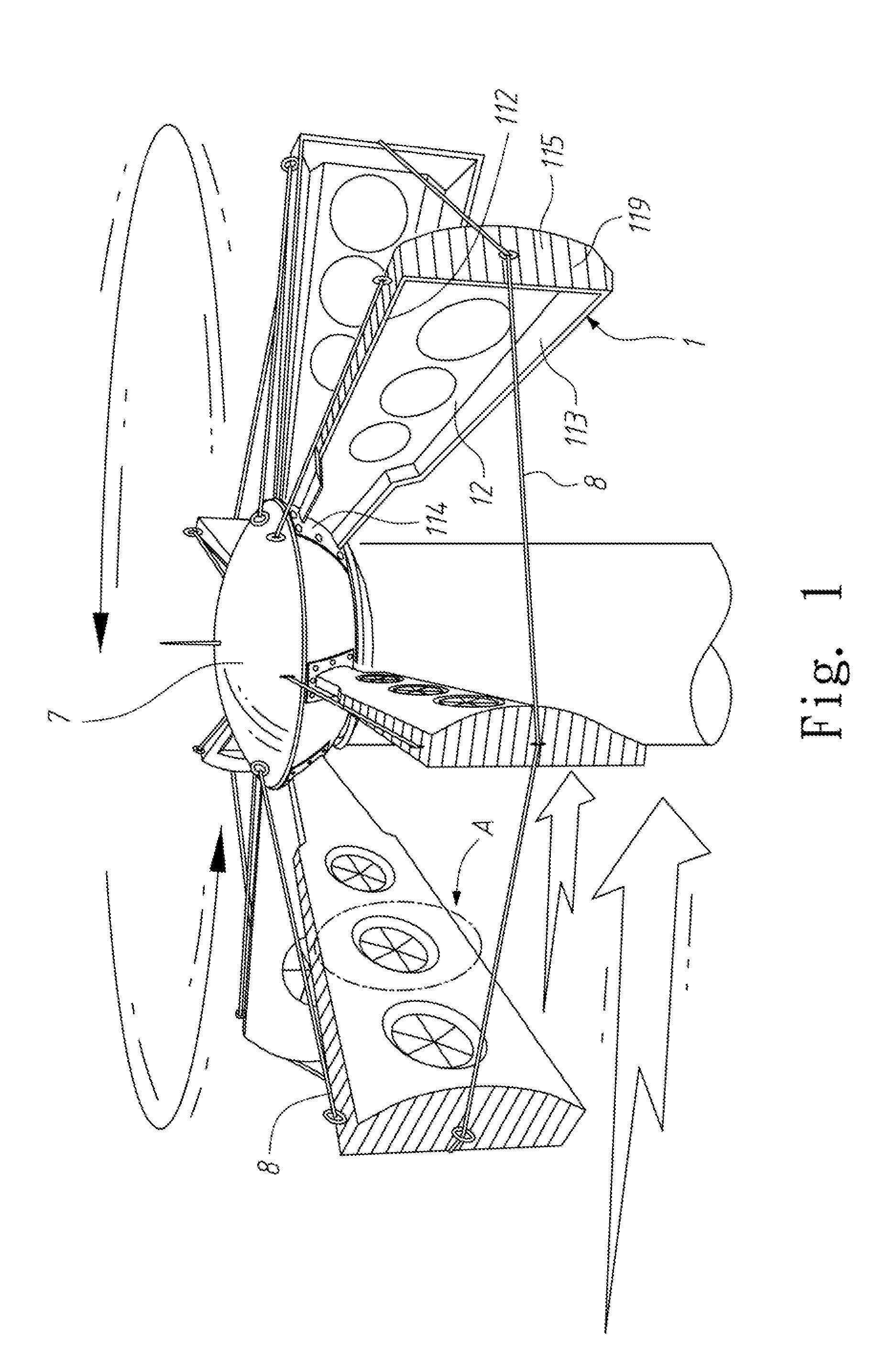
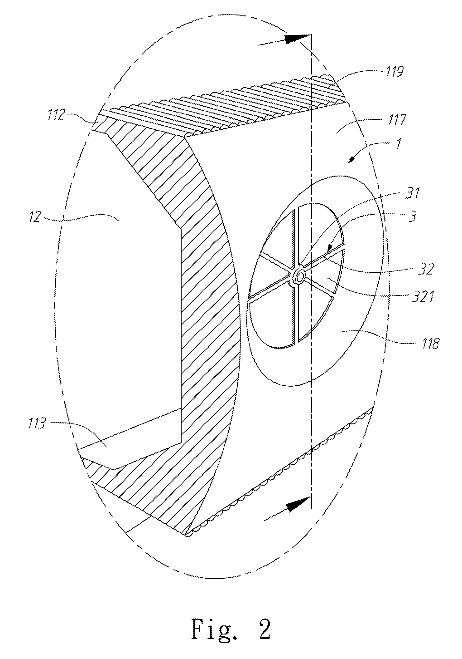
[0031]Please refer to FIG. 1 that is a fragmentary perspective view showing a plurality of vanes according to the present invention is mounted around and spaced along a main shaft 7 of a wind power generator, and to FIG. 2 that is an enlarged and partially sectioned perspective view of the circled area A of FIG. 1, and to FIGS. 3 to 5 that are sectioned side views of one vane according to a first embodiment of the present invention.

[0032]As shown, the vane structure for vertical axis wind power generator according to the first embodiment of the present invention includes a plurality of vanes, each of which includes a vane body 1, a first arcuate guide bar 2, an openwork screen 3, and a first movable baffle unit 4.

[0033]The vane body 1 includes a body port...


PUM


Abstract

A vane for vertical axis wind power generator includes a vane body defining a rearward recess and having a front plate portion with a through hole; a first arcuate guide bar located in the recess with a second end connected to the vane body and a first end located in the through hole; an openwork screen fitted in the through hole and connected to the first end of the first arcuate guide bar; and a first movable baffle unit slidably fitted around the first arcuate guide bar and pivotally connected to the vane body to openably cover the openwork screen. When the rearward recess is against the wind, the first movable baffle unit covers the openwork screen for the rearward recess to effectively intercept the wind. When the rearward recess is before the wind, the first movable baffle unit naturally opens to reduce the air resistance to the vane.

Description

RELATED APPLICATIONS[0001]This application claims priority to China Application Serial Number 200810180782.6, filed Dec. 2, 2008, which is herein incorporated by reference.FIELD OF THE INVENTION[0002]The present invention relates to a vane structure for a vertical axis wind power generator, and more particularly to a vane for vertical axis wind power generator that includes a movable baffle unit to close or open a through hole on the vane to thereby effectively intercept the wind or reduce the air resistance to the vane, respectively.BACKGROUND OF THE INVENTION[0003]A vertical axis wind power generator has a vertical main shaft, on which a plurality of vanes are mounted to space from one another along a circumferential surface of the main shaft. Each of the vanes has a front side and a rear side that are generally two corresponding outward curved face and inward curved face, respectively. The inward curved face of the vane is located against the wind to intercept the flow of air cur...

Claims


Application Information

Patent Timeline
Patent Type & Authority Applications(United States)
IPC IPC(8): F01D5/14
CPCF01D5/145F03D3/005F03D3/061F05B2240/30F05B2240/313F05B2260/30F05D2260/52F05B2260/96F05D2270/17Y02E10/74F05D2240/30F05D2260/96F05D2260/30F05B2260/502F03D3/067F05B2240/211
Inventor YEH, DONG-HUA
Owner YEH DONG HUA
Why Eureka
Try Eureka