System and method for predicting fluid flow characteristics within fractured subsurface reservoirs

a reservoir and fluid flow technology, applied in the direction of cad techniques, instruments, borehole/well accessories, etc., can solve the problems of affecting the simulation effect of full-field simulation models, difficult hydrocarbon passage through formation, and inability to accurately predict the fluid flow characteristics of fractured subsurface reservoirs

Active Publication Date: 2010-06-03
CHEVROU USA INC
View PDF25 Cites 135 Cited by
  • Summary
  • Abstract
  • Description
  • Claims
  • Application Information

AI Technical Summary

Problems solved by technology

Highly complex geological subsurface reservoirs, such as reservoirs having a network of fractures, present unique and specialized challenges with regards to forecasting fluid flow characteristics.
As discussed later in more detail herein, these challenges arise due to characterization, gridding, discretization, and simulation of the network of fractures within a reservoir.
Subsurface reservoirs with a network of fractures typically have a low permeability rock matrix, making it difficult for hydrocarbons to pass through the formation.
However, realistic geological characterizations of the reservoir are generally too computationally expensive for direct flow simulation of full-field simulation models because current reservoir simulators are encumbered by the level of detail contained in realistic geological characterizations.
In particular, these, simulations are hindered due to the presence of large models and the high contrast in matrix and fracture permeabilities.
This can further be compounded by multiphase flow (oil, gas, solvent, and water), the need to use hydrocarbon pseudo phases to represent first-contact miscible fluids (oil and solvent), the inclusion of complex physics to compensate for gravity and capillarity effects on fluid flow, and complicated producing rules based on actual field development plans.
However, while these attempts may allow for a reduced computational time, they typically are based off of simplifying assumptions that result in less reliable forecasts of the fluid flow characteristics.

Method used


Image

  • System and method for predicting fluid flow characteristics within fractured subsurface reservoirs
  • System and method for predicting fluid flow characteristics within fractured subsurface reservoirs
  • System and method for predicting fluid flow characteristics within fractured subsurface reservoirs

Examples


examples

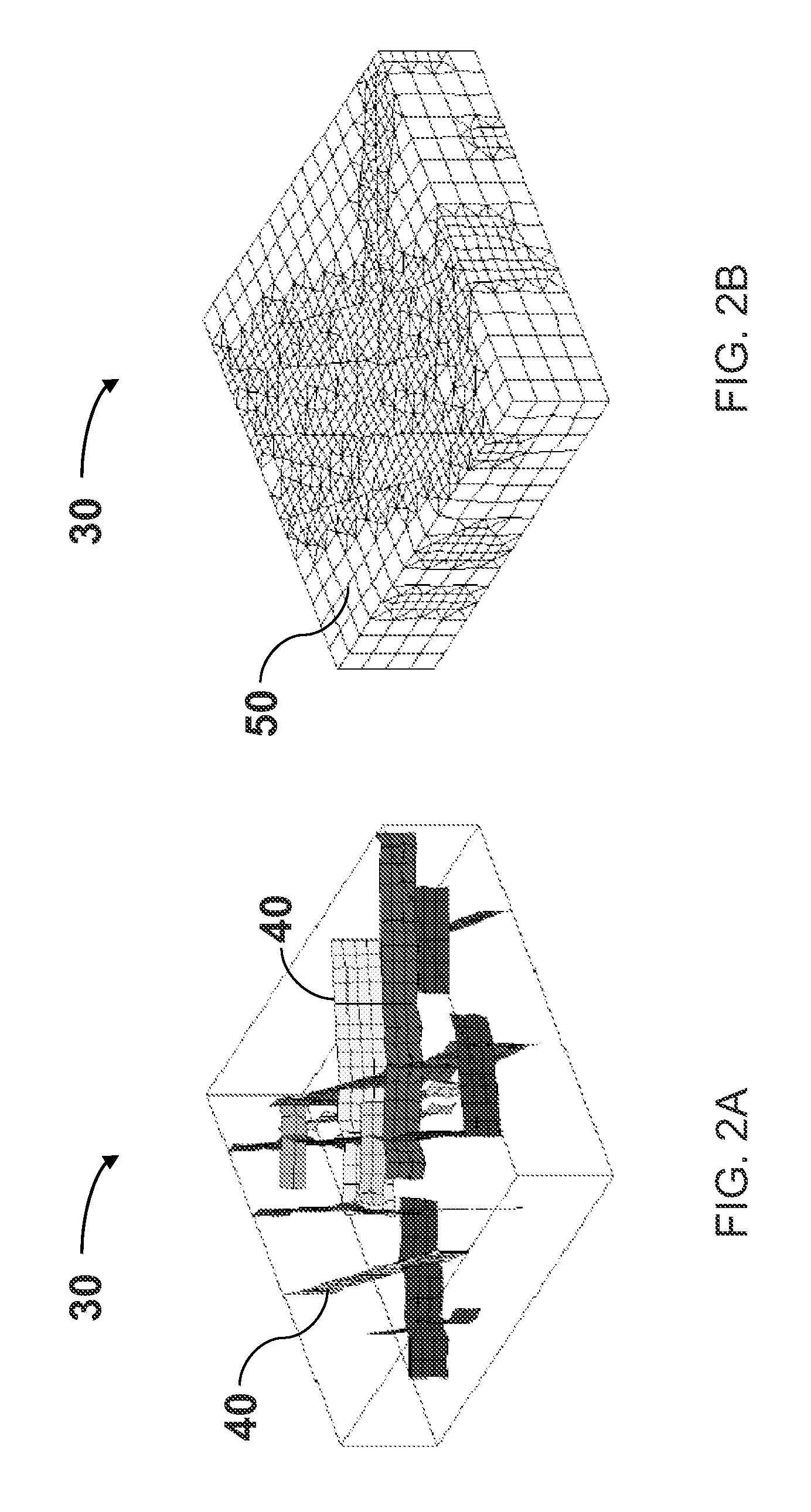
[0060]Referring to FIG. 4, the system and method as described in FIG. 1 is applied to a giant carbonate reservoir to predict fluid flow characteristics. In particular, a sector encompassing a region of interest, which is approximately 17 mi×1.4 mi×1.1 mi in physical dimension and represents about 1 / 15th of the full-field model, is investigated. As in Step 11 of Method 10, geological data describing the sector is provided. Using the fracture characterization procedure, a network of hundreds of discrete fractures is stochastically generated, similar to that which is performed in Step 13 of Method 10. A realistic discrete fracture model 200 is constructed to represent the carbonate reservoir. The realistic discrete fracture model 200 is an example of a fine-scale geological model of the subsurface reservoir that is constructed in Step 15 of Method 10. The model contains 1230 discrete fractures, represented by reference character 210, and 47 current or future planned wells (8 fluid inje...


PUM


Abstract

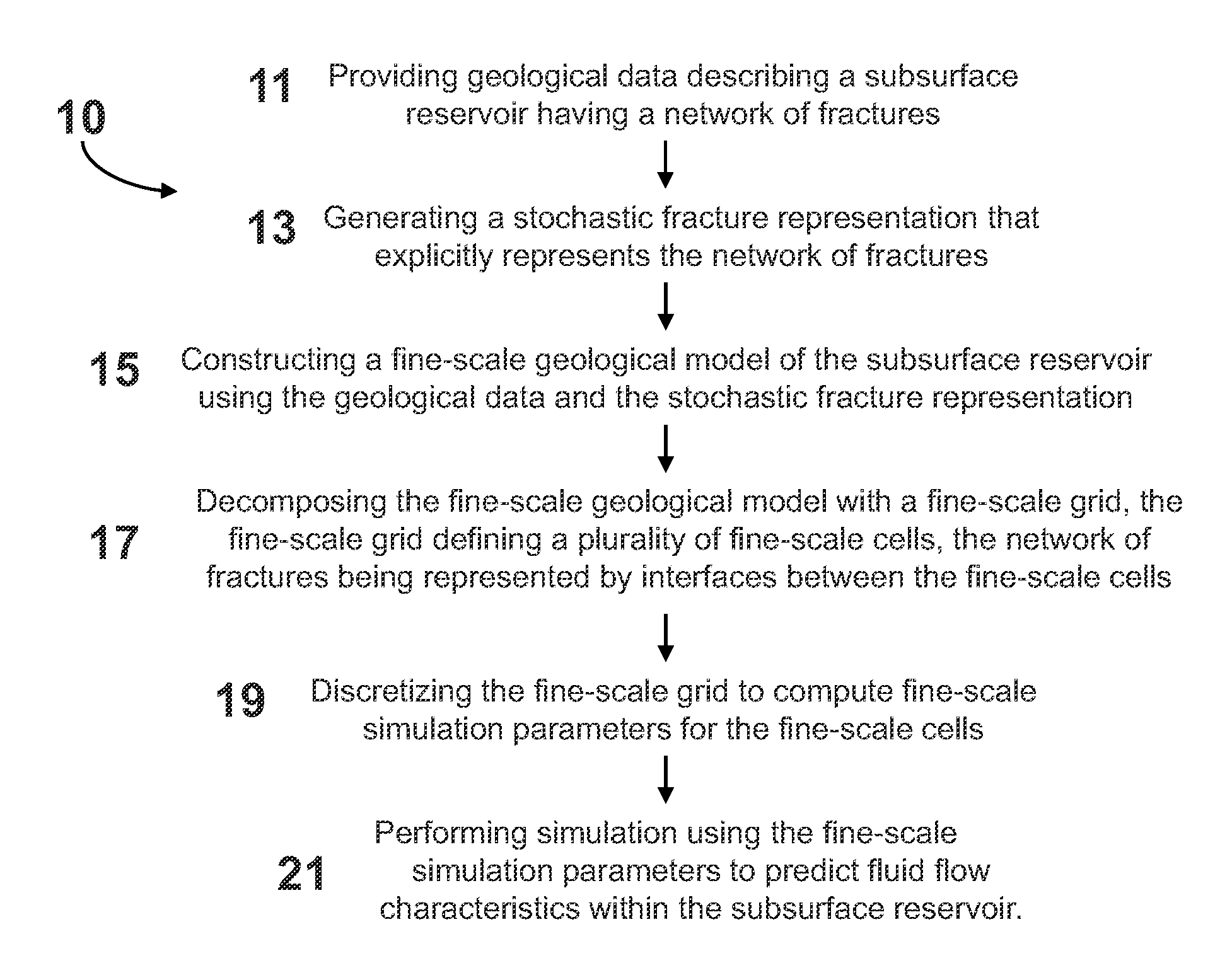
A system and method having application notably towards predicting fluid flow characteristics within fractured subsurface reservoirs. The system and method include steps of reservoir characterization, gridding, discretization, and simulation of geologically realistic models describing the fractured subsurface reservoirs. A stochastic fracture representation that explicitly represents a network of fractures within a subsurface reservoir is constructed and used to build a fine-scale geological model. The model is then gridded such that the network of fractures is represented by interfaces between the fine-scale cells. The model is the discretized and simulated. Simulation can be on a fine-scale or on an upscaled course-scale to produce efficient and reliable prediction of fluid flow characteristics within the subsurface reservoir.

Description

CROSS-REFERENCE TO RELATED APPLICATION[0001]The present application for patent claims the benefit of U.S. Provisional Applications for Patent bearing Ser. Nos. 61 / 119,604 and 61 / 119,615, both filed on Dec. 3, 2008, which the entirety of both applications are incorporated herein by reference.FIELD OF THE INVENTION[0002]The present invention generally relates to a system and method for predicting fluid flow characteristics within subsurface reservoirs, and more particularly, to a system and method for predicting fluid flow characteristics within fractured subsurface reservoirs.BACKGROUND OF THE INVENTION[0003]The field of hydrocarbon production is directed to retrieving hydrocarbons that are trapped in subsurface reservoirs. Typically, these reservoirs are comprised of parallel layers of rock and fluid material each characterized by different sedimentological and fluid properties. Hydrocarbons accumulate below or between non-porous or lower permeability rock layers, forming reservoirs...

Claims


Application Information

Patent Timeline
Patent Type & Authority Applications(United States)
IPC IPC(8): G06G7/50
CPCE21B43/00E21B43/26G06F2217/16G06F17/5018E21B49/00G06F2111/10G06F30/23G01V1/28G06F30/28
Inventor HUI, MUN-HONGMALLISON, BRADLEY THOMAS
Owner CHEVROU USA INC
Why Eureka
Try Eureka