
Active Sensor, Use Thereof and Method for Compensating Amplitude Fluctuations in the Output Current Signal of an Active Sensor

a technology of active sensors and output current, applied in the field of active sensors, can solve the problems of relatively complex circuits, low signal transmission efficiency, and low signal transmission efficiency

Inactive Publication Date: 2010-06-10
CONTINENTAL TEVES AG & CO OHG
View PDF7 Cites 5 Cited by
  • Summary
  • Abstract
  • Description
  • Claims
  • Application Information

AI Technical Summary

Benefits of technology

[0009]By superimposing the compensating current on the output current signal, an output current of defined amplitude can be set independently of essentially external influences, for example due to the temperature or aging influences. Unwanted amplitude fluctuations or changes in the amplitudes of the output current signal of the active sensor can thus be avoided. This makes it possible to guarantee that the amplitude-coded output information of the active sensor can be decoded correctly by the respective receiver, for example the electronic control unit of a motor vehicle control system. This is particularly relevant when using the sensor in safety-critical systems such as, for example, a motor vehicle control system. Amplitude fluctuations of the output current signal no longer need to be compensated for almost completely or with relatively great expenditure by means of a relatively elaborate calibration as has previously been common practice. Neither do production inaccuracies of electronic components need to be corrected, especially by trimming, due to the adjustment of a defined output signal amplitude according to aspects of the invention.
[0014]The input of the current sensing device is suitably connected to the input line and / or output line between the measuring module and the first or the second node. By this means, the current sensing device is able to sense the load current of the measuring module in a relatively simple manner.
[0019]It is preferred that the compensating device can generate, as an alternative to the first compensating current at the first output path or additionally at at least one additional output path connected to the second node, at least one second compensating current which differs from the first compensating current. In this arrangement, the compensating currents are different by a defined, in each case mutually different scaling factor from the current provided at the second output path of the compensating device. In particular, the compensating currents are greater by in each case a mutually different scaling factor than the current provided at the second output path. In this arrangement, it is possible to switch between these compensating currents as a result of which the output current signal can be adjusted or corrected to different amplitudes in a relatively simple manner.

Problems solved by technology

However, the proposed circuit is relatively complex and provides at the output side voltage signals which, according to experience, are not very suitable for signal transmission.
In addition, this proposed circuit cannot compensate for amplitude fluctuations in the signal processing output signals, caused, for example, by aging or temperature influences.

Method used


Image

  • Active Sensor, Use Thereof and Method for Compensating Amplitude Fluctuations in the Output Current Signal of an Active Sensor
  • Active Sensor, Use Thereof and Method for Compensating Amplitude Fluctuations in the Output Current Signal of an Active Sensor
  • Active Sensor, Use Thereof and Method for Compensating Amplitude Fluctuations in the Output Current Signal of an Active Sensor

Examples


Embodiment Construction

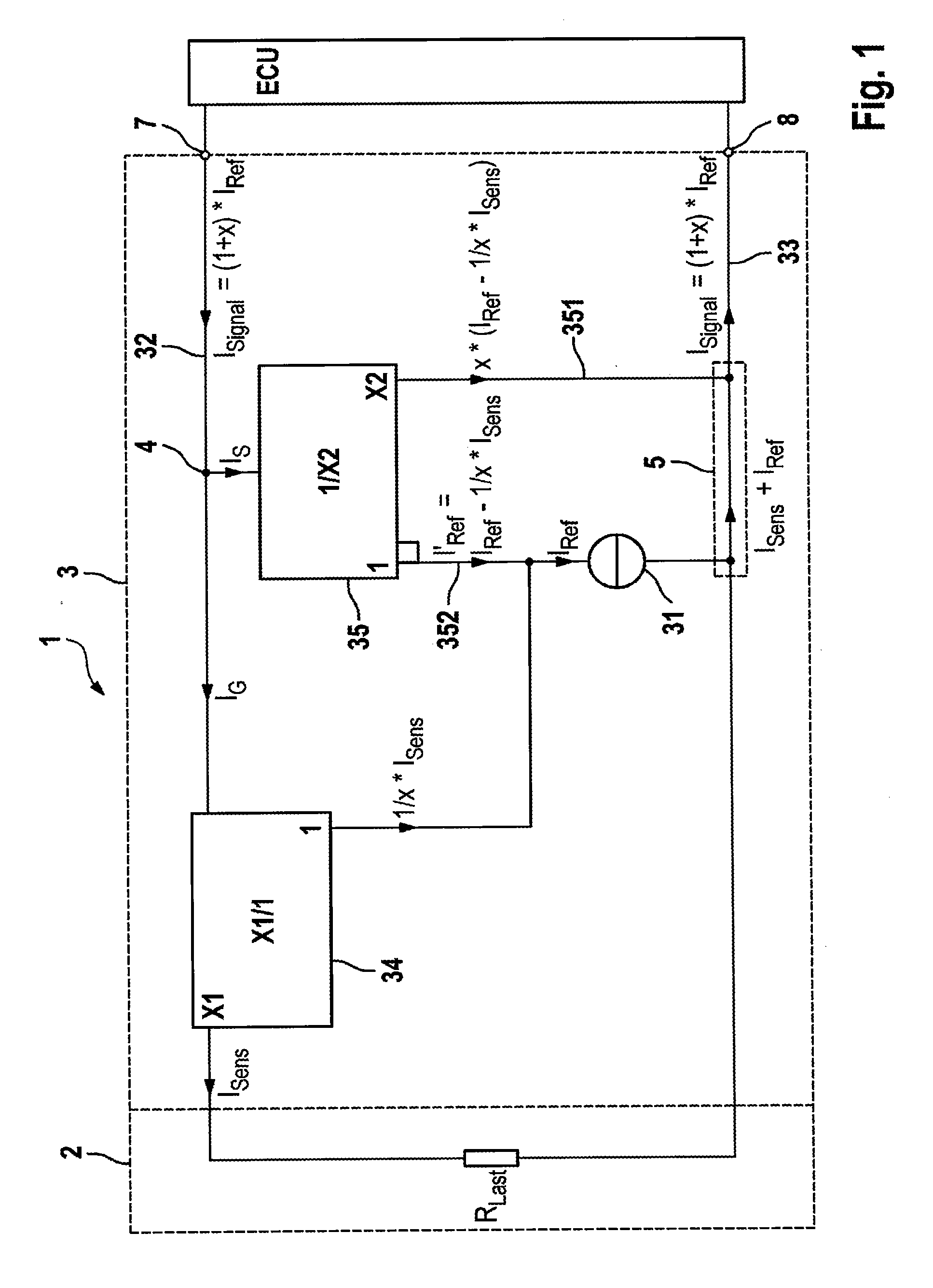
[0037]The exemplary, active sensor shown in FIG. 1 is used for illustrating the basic operation. The active sensor 1 is connected to the electronic control unit of a motor vehicle control system ECU by means of a two-wire line and is supplied with energy via these two lines. In addition, all information is also exchanged between the active sensor 1 and the ECU via these two lines. This particularly refers to the output information of the active sensor 1. These two connecting lines are connected to the active sensor 1 by means of terminals 7 and 8. As an extension of these two connecting lines and connected to terminals 7 and 8 on the sensor side, interface module 3 has an input line 32 and an output line 33. The measuring module 2, the entire load impedance of which is combined and illustrated by the resistance Rload, is connected to these two lines on the sensor side. At node 4 of the input line 32, the inputs of the current sensing device 34 and of the compensating device 35 are c...


PUM


Abstract

An active sensor consisting of a measuring module and an interface module comprising at least one first current source, an input line and an output line, wherein the active sensor is supplied with energy via these two lines and the first current source is connected on the output side to the output line and the interface module generates the output signals of the active sensor in the form of current signals, wherein the interface module comprises a current sensing device which senses the load current of the measuring module, and a compensating device which can generate, on an output path connected to the output line, a first compensating current for compensating for amplitude fluctuations in the output current signals in dependence on the sensed load current of the measuring module. Also described is a method for compensating for amplitude fluctuations in the output current signals of an active sensor.

Description

CROSS REFERENCE TO RELATED APPLICATIONS[0001]This application is the U.S. national phase application of PCT International Application No. PCT / EP2007 / 062908, filed Nov. 27, 2007, which claims priority to German Patent Application No. DE102006056452.9, filed Nov. 28, 2006 and German Patent Application No. DE102007026788.8, filed Jun. 9, 2007, the contents of such applications being incorporated by reference herein.BACKGROUND OF THE INVENTION[0002]1. Field of the Invention[0003]The invention relates to an active sensor and the use of the active sensor, particularly as wheel speed sensor, in motor vehicles.[0004]2. Description of the Related Art[0005]WO 98 / 08711 describes an active rotational-speed sensor which is connected to an electronic control unit via two lines and is supplied with energy and transmits the output signals via these two lines. The active sensor has a signal processing circuit and a current interface. In this arrangement, the adjustment of defined amplitudes of the o...

Claims


Application Information

Patent Timeline
Patent Type & Authority Applications(United States)
IPC IPC(8): G01R19/00
CPCB60T8/171G01P21/02G01P3/489B60T8/32G01P3/48
Inventor DIETZ, TIMOJOCKEL, WOLFGANGKLAUSEN, RALF
Owner CONTINENTAL TEVES AG & CO OHG
Learn More