
Method for data and signal transfer between different sub-units of a medically-related system

a technology applied in the field of data and signal transmission between different sub-units of a medically related system, can solve the problems of future improvement and expansion of such a system, and achieve the effect of reducing the number of necessary connections and great expenditur

Active Publication Date: 2010-03-02
SIEMENS HEALTHCARE GMBH
View PDF16 Cites 2 Cited by
  • Summary
  • Abstract
  • Description
  • Claims
  • Application Information

AI Technical Summary

Benefits of technology

[0009]An object of the present invention is to provide a method for data and signal transfer between different sub-units of a medically-related system that enables expansion for later developments on the system without great expenditure and that additionally significantly reduces the number of necessary connections.
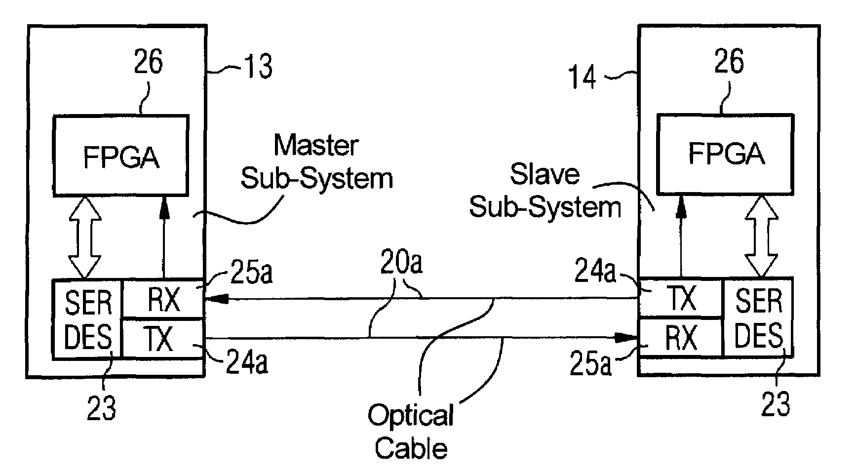
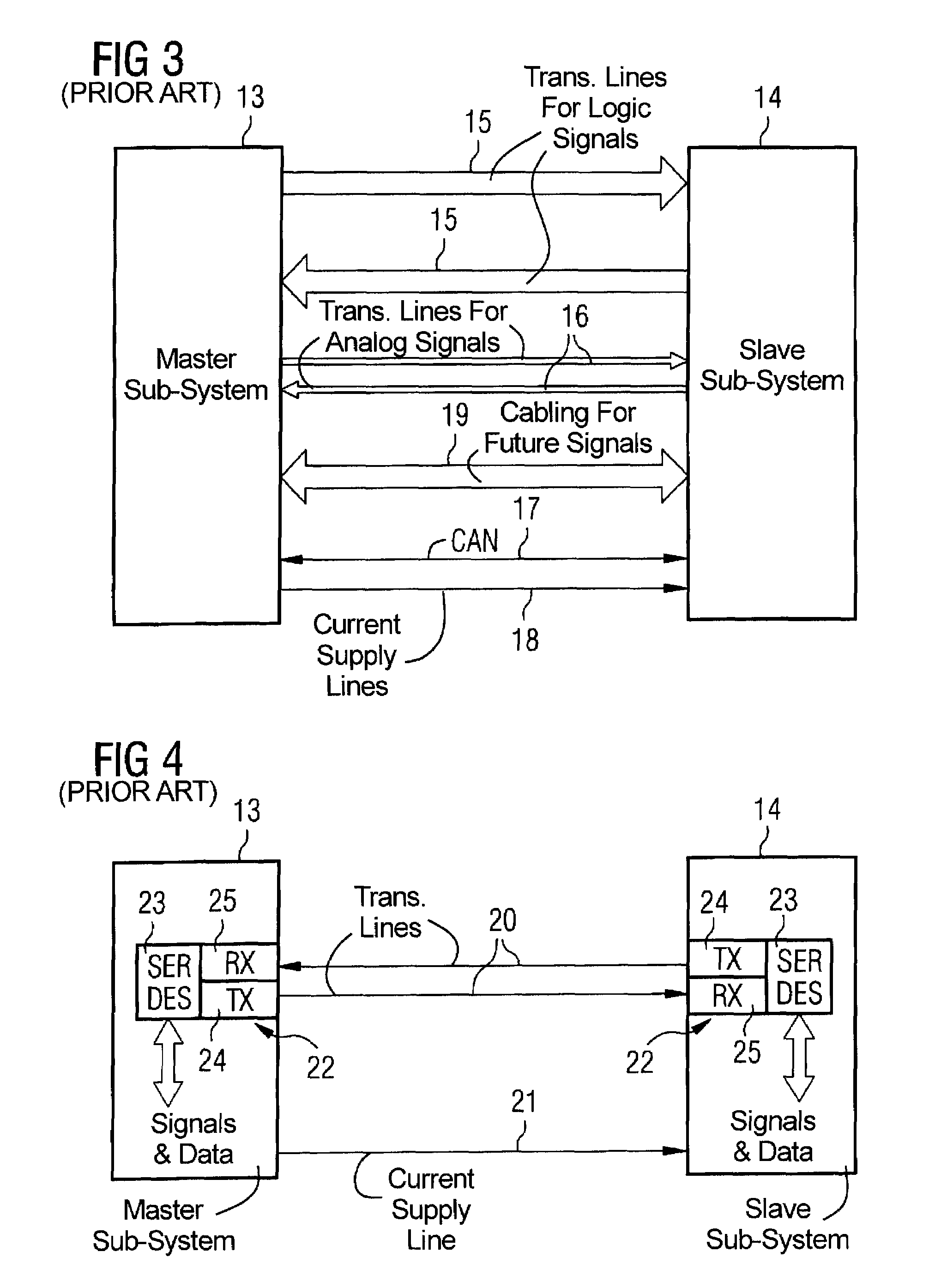
[0010]This object is achieved in accordance with the invention by a method and system for data and signal transfer between different sub-units of a medically-related system, wherein digitized analog and / or logical signals and digital data are mutually transmitted on a transfer line by means of serial multiplexing. The digitized analog and / or logical signals and the digital data are transmitted combined into individual packets that respectively contain both bits of the digitized signals and bits of the digital data, and that have a length that is small enough, in terms of the total number of bits per packet, so that adherence to a predetermined updating rate of the logic signals is achieved.
[0011]With this solution it is possible to transfer all signals (in particular control signals) to be exchanged between the individual sub-units and data over a single transmission line—if necessary with a separate return line for the opposite communication, which, however, also can be carried on the same transmission line. In principle all further connection lines can be avoided (with the exception of a line for the electrical voltage supply) via the bidirectional transfer both of the analog and / or logical signals in digitized form and of the digital data by means of the serial multiplexing over one or two transfer lines with high speed. This reduces the problem of the electromagnetic compatibility in electrical signal lines and improves the reliability of the transfer due to the lower number of components that are necessary for each interface. Due to the reduction of the number of physical components as well as connections for each interface to a minimum, the production, the testing as well as the servicing of the system are also simplified. If all analog and logic signals to be transferred in the system are transferred with the present method, a galvanic insulation between the individual sub-units on the signal plane is also achieved due to the necessary digitization of these signals. A particular advantage of the present method is the easy expansion capability of a system that is achieved by the method, since further signals or data can be implemented in the packets to be transferred without any further steps or modifications.

Problems solved by technology

This leads to a multiplicity of connections with respectively different protocols that make future improvement and expansion of such a system more difficult.

Method used


Image

  • Method for data and signal transfer between different sub-units of a medically-related system
  • Method for data and signal transfer between different sub-units of a medically-related system
  • Method for data and signal transfer between different sub-units of a medically-related system

Examples


Embodiment Construction

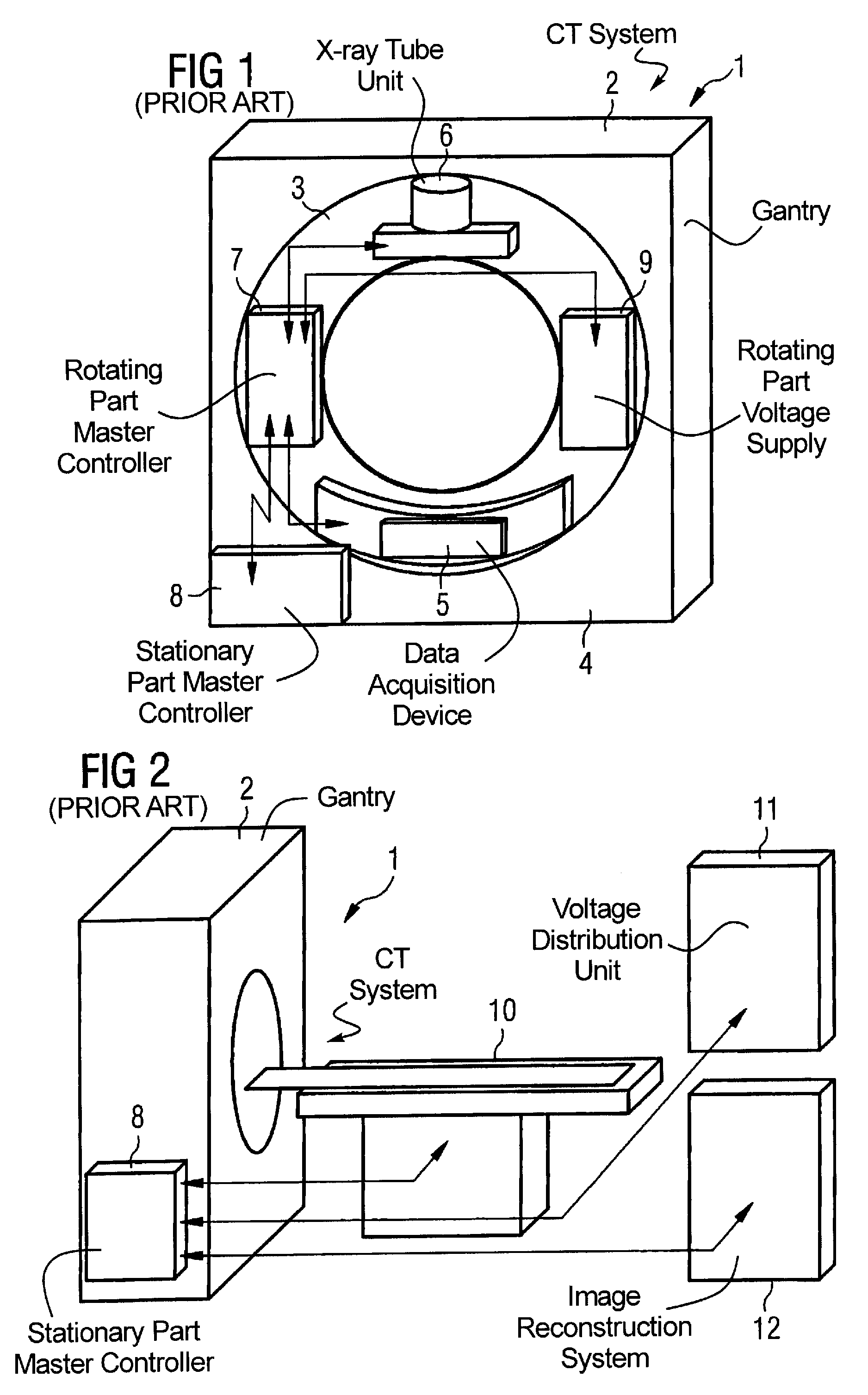
[0026]The present method is subsequently described in detail using a CT system that is visible in schematic representation in FIGS. 1 and 2.

[0027]FIG. 1 shows the gantry 2 of a CT system 1 with a rotating part 3 as well as a stationary part 4. An x-ray tube unit 6 as well as a data acquisition device 5 opposite thereto are visible within the rotating part 3. The x-ray tube unit 6 includes an x-ray tube, a collimator, a focus control device as well as a device for anode rotation. The data acquisition device 5 includes the x-ray detector as well as the associated evaluation unit. Furthermore, a master controller 7 for the rotating part 3 and for dose modulation, a voltage supply 9 with a radio-frequency generator and a voltage source for the rotation are disposed on the rotating part 3 of the gantry 2. The individual control signals and / or data are transferred from the master controller 7 to the respective sub-units and are received by these sub-units, as this is indicated by the arro...


PUM


Abstract

In a method and system for data and signal transfer between different sub-units of a medically-related system, in particular a CT system, digitized signals and digital data are transmitted together on a transmission line by means of serial multiplexing. The digitized signals and the digital data are transferred combined into individual packets having a length that is so small that the adherence to a predetermined updating rate of the signals is achieved. The expenditure for the wiring as well as for future expansions in medically-related systems can be significantly reduced.

Description

BACKGROUND OF THE INVENTION[0001]1. Field of the Invention[0002]The present invention a method for data and signal transfer between different sub-units of a medically-related system, in particular a CT system, as well as a medically-related system in which the method is implemented.[0003]2. Description of the Prior Art[0004]Medically-related systems, in particular modern CT systems, include a number of connection lines between the individual sub-units, via which signals are transmitted for the activation of components of the system, as well as for the transfer of digital data such as, for example, measurement data. Due to the continuing development, CT systems require a flexible and expandable architecture that should be directed toward high reliability as well as toward a simple implementation of service tasks, and additionally should limit the cost expenditure for expansions.[0005]Just like the other, medically-related systems, for example in the field of magnetic resonance tomogr...

Claims


Application Information

Patent Timeline
Patent Type & Authority Patents(United States)
IPC IPC(8): G06F13/38G06F3/00H04J14/08H05G1/60H04L12/28A61B6/00A61B6/03H04J3/24H04L5/22H04L12/40H04L12/413H04L12/56
CPCH04J3/247
Inventor GROTTEL, JOACHIMGRUBER, KLAUSPOPESCU, STEFAN
Owner SIEMENS HEALTHCARE GMBH
Learn More