Method for operating a communications network and network arrangement

a communication network and network arrangement technology, applied in the direction of digital transmission, data switching network, electrical apparatus, etc., can solve problems such as network infrastructure overloaded, nodes in the network being used are faulty, and inconsistent data errors

Active Publication Date: 2018-06-12
SIEMENS AG
View PDF20 Cites 2 Cited by
  • Summary
  • Abstract
  • Description
  • Claims
  • Application Information

AI Technical Summary

Benefits of technology

[0017]The monitoring of the data transmission rate and the potential blocking of data reception make it possible to handle, in particular, what are referred to as “Babbling Idiots”, that is to say network devices present in the network which due to a defect transmit meaningless data or data which cannot be interpreted by other devices in the network.
[0065]Overall, a particularly reliable network arrangement, which functions reliably even in the case of disruptions of communication channels is obtained. The redundant ring-shaped communication path device permits consistent control device communication and fault analysis and correction which are favorable in terms of expenditure and handling of faults due to Babbling Idiots in a way which is favorable in terms of expenditure.

Problems solved by technology

In this respect, errors in the form of inconsistent data, which may be corrupted, for example, in the case of data transmission via the network which is being used, have to be detected.
Furthermore, it is possible that nodes in the network being used are faulty.
The network infrastructure can be overloaded by high data rates in such a way that genuine control data or sensor data can no longer be exchanged between the still functioning network devices.
In the past, methods were proposed in which the data exchange between predefined communication partners was bandwidth-limited.
Defective network nodes can, however, also generate data packets with inadequate address data, and within the scope of a dedicated bandwidth limitation, this cannot be handled satisfactorily in every network topology, in particular, not in a ring-shaped network topology.
Such timeslot methods require complex synchronization and special hardware devices.
This “meaningless” data is often output at high frequency by the faulty devices, with the result that the network infrastructure and communication paths can become overloaded.
In this respect, redundant forwarding and checking of the functional capability of all the network devices involved becomes possible.

Method used


Image

  • Method for operating a communications network and network arrangement
  • Method for operating a communications network and network arrangement
  • Method for operating a communications network and network arrangement

Examples


first embodiment

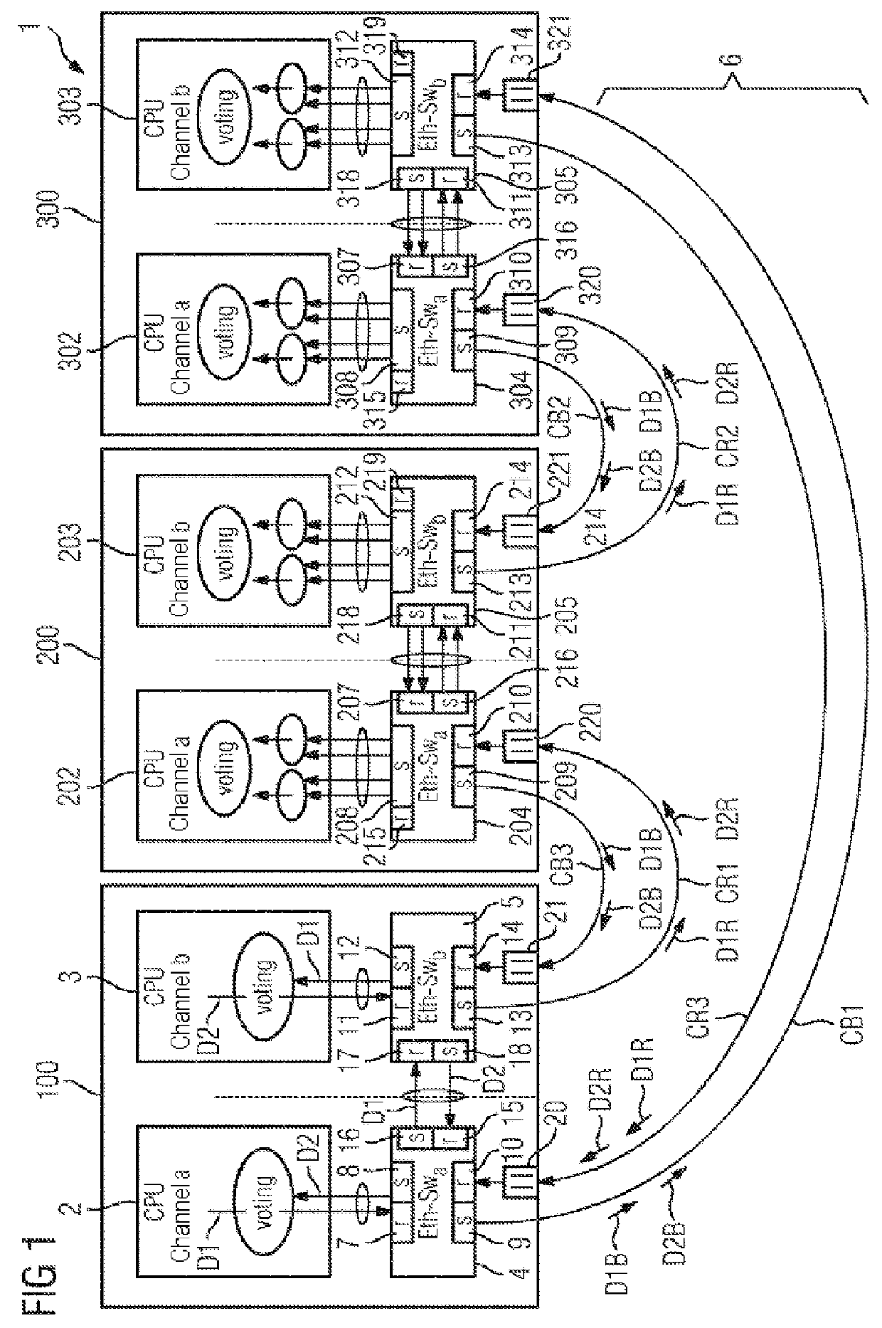
[0083]In the figures, identical or functionally identical elements have been provided with the same reference symbols unless stated otherwise. FIG. 1 illustrates a schematic illustration of a network arrangement. The figures also serve to explain the method for operating the network arrangement.

[0084]FIG. 1 shows a network arrangement 1 which can be used, for example, as an Ethernet network in a vehicle. In this context, for example three network devices 100, 200, 300 are illustrated. These can be, for example, control components. The network devices 100, 201, 301, which are also referred to below as network nodes or control components, each have redundant control devices 2, 3, 202, 203, 302, 303. The network devices 100, 201, 301 can also be referred to as subscribers of the network.

[0085]The control devices 2, 3, 202, 203, 302, 303 are adapted in order to perform certain tasks or functions. This may be, for example, sensor detection or an actuator. They can also be implemented as ...

fourth embodiment

[0117]FIG. 6 shows a schematic illustration of a network arrangement 102. The network arrangement 102 has four network devices 400. The respective network device 400 can be based on one of the exemplary embodiments in FIGS. 1-5. The network devices 400 can have different functionalities. For example, the two upper network devices 400 in FIG. 6 can be embodied as control computers and the two lower network devices 400 as actuators. The left-hand network devices 400 are part of a first network segment 701. In contrast, the right-hand network devices 400 are part of a second network segment 702.

[0118]In the middle region (inner region) of the respective network segment 701, 702, first fuse devices F1 are provided which have a higher threshold value for the data transmission rate than those fuse devices F2 which are arranged in the edge region of the respective network segment 701, 702. Accordingly, the first fuse devices with the higher threshold value F1 for the internal communication...

fifth embodiment

[0119]FIG. 7 shows a schematic illustration of a network arrangement 102.

[0120]The network arrangement 102 in FIG. 7 has twelve network devices 811-814, 821-822, 831-832, 841-842, 851-852 with different functionalities. The network devices 811-814 are embodied as control computers. The network devices 821-822 form a node of a first type, the network devices 831, 832 form a node of a second type and the network device 841, 842 form a node of a third type. The network devices 851, 852 are embodied as coupling switches.

[0121]In addition, the network arrangement 102 has four implemented virtual networks V1-V4. In this context, the reference symbols V1-V4 in FIG. 7 illustrate which virtual lines are associated with which virtual network V1-V4.

[0122]In addition, five different fuse devices F1-F5 with different threshold values are used in the network arrangement 102. The first fuse device F has, for example, a threshold value of 80% of the predefined maximum data transmission rate of the ...


PUM


Abstract

A method for operating a communications network, in particular an Ethernet network is provided. Network devices that are coupled to the network have a switch device and a control device that is coupled to the switch device, and the switch device has at least one receiving port and a sending port for sending and receiving data via the communications network. Fuse devices for monitoring a particular data transfer rate are assigned to the receiving ports. The fuse devices block data reception at a particular receiving port when a previously determined maximum data transfer rate is exceeded. A possible annular structure using bidirectional communication paths and the limitation of the data transfer rate at the receiving ports improve fail-safety and error analysis in the event of transfer and hardware errors, in particular babbling idiot errors. The invention further relates to a network arrangement having a plurality of corresponding network devices which function according to said method.

Description

CROSS-REFERENCE TO RELATED APPLICATIONS[0001]This application claims priority to PCT / EP2012 / 069273, having a filing date of Sep. 28, 2012 which claims priority to DE Patent Application 10 2012 000 185.1 having a filing date of Jan. 9, 2012, the entire contents of each which are hereby incorporated by reference.FIELD OF TECHNOLOGY[0002]The following relates to a method for operating a communications network and to a network arrangement which operates with the proposed method. The method for operating can be used, in particular, in an Ethernet environment.BACKGROUND[0003]Communications networks are finding ever broader application for measuring and performing open-loop and closed-loop control of complex technical systems. For example, increasingly networks are being used in motor vehicles in order to form vehicle control systems. In corresponding complex and safety-relevant technical systems stringent requirements are made of the availability of the control elements which are provided...

Claims


Application Information

Patent Timeline
Patent Type & Authority Patents(United States)
IPC IPC(8): H04L12/801H04L12/939H04L12/413H04L45/586
CPCH04L47/29H04L49/55H04L12/413
Inventor ARMBRUSTER, MICHAELFIEGE, LUDGERRIEDL, JOHANNESSCHMID, THOMASZIRKLER, ANDREAS
Owner SIEMENS AG
Why Eureka
Try Eureka