Reinforced section

a technology for supporting frames and profiles, which is applied in the direction of roofs, transportation and packaging, vehicle arrangements, etc., can solve the problems of high cost of single-part production and assembling parts, high and inability to vary the dimensions of reinforcing profiles with considerable expenditure, so as to achieve the effect of increasing the rigidity of the vehicle supporting frame, reducing manufacturing costs, and reducing the number of welded parts

Active Publication Date: 2008-11-25
THYSSENKRUPP STEEL EURO AG
View PDF40 Cites 2 Cited by
  • Summary
  • Abstract
  • Description
  • Claims
  • Application Information

AI Technical Summary

Benefits of technology

[0004]The object of the invention is therefore to provide a reinforcing profile of the type mentioned at the outset, by means of which the rigidity of the vehicle supporting frame is effectively increased, and which is distinguished by lower manufacturing costs and furthermore may be varied in its dimensions without great expenditure.
[0006]The reinforcing profile according to the invention, even in the case of complex three-dimensional shaping, comprises a simple basic body, namely the one-piece double shell produced with the aid of hydroforming technology. As a result of the high variability with respect to the shape to be produced it is possible to form the rounded corner reinforcements, necessary for improved support and uniform force progression between the two pillars of the vehicle structure, in one piece with the reinforcing profile, whereby large pillar connection zones are produced that can be efficiently used. In contrast to the prior art, no further component parts thus have to be produced and assembled in addition to the actual profile, so the production costs may be considerably reduced. A further consequence of said variability is that the dimensions of the reinforcing profile may be adapted comparatively easily to the user's specifications. This applies to the radius of the rounded portion as well as to the height of the profile. In addition, the number of joins can be reduced to a minimum with the one-piece construction of the reinforcing profile, so the rigidity of the base material, in particular when using higher strength steel materials, can be optimally utilised and thus outstanding supporting properties can be attained.
[0008]According to an advantageous configuration of the invention, at the base, the reinforcing profile also comprises edge regions bent at a right angle for connecting to the base panel of a vehicle body. These regions form connection zones that can be efficiently used, for example for a welded, soldered or glued joint.
[0013]With hydroforming technology a method is used which allows the user a high degree of freedom of design with respect to the form to be produced. The particular advantage of hydroforming technology in relation to the material properties of the reshaped component, for example with respect to deep drawing, lies in the fact that the material to be reshaped is stretched much more intensively and homogeneously in the case of hydroforming. As a result of this material stretching, the “bake hardening” effect, i.e. the additional increase in rigidity with a heat treatment at relatively low temperatures, for example by paint stoving, can, in particular in the case of higher strength steels, be intensified. The rigidity values that can be achieved thereby allow a further reduction in the requisite material strengths and thus contribute to a reduction in the overall weight of the vehicle.
[0014]According to an advantageous configuration of the method it is provided that the peripheral edge of the double blank is welded at the end face by laser beam welding. This is a reliable joining method that can be well automated.

Problems solved by technology

High costs both for the single-part production and for assembling the parts are associated with the large number of different parts.
In addition, varying of the reinforcing profile dimensions is only possible with considerable expenditure as for this purpose newly configured tools have to be provided in each case for the component parts.
Finally, the high number of welded joints, as a result of the construction, has an adverse effect, in particular when using higher strength steel materials as the base material as these are a lot less rigid compared with the base material and therefore constitute a factor that reduces the fatigue strength of the construction.

Method used


Image

  • Reinforced section
  • Reinforced section
  • Reinforced section

Examples


Embodiment Construction

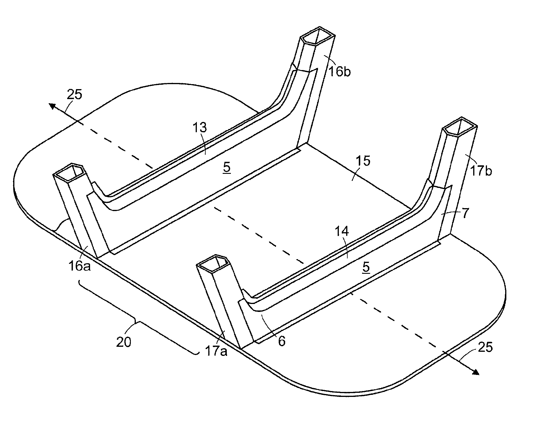
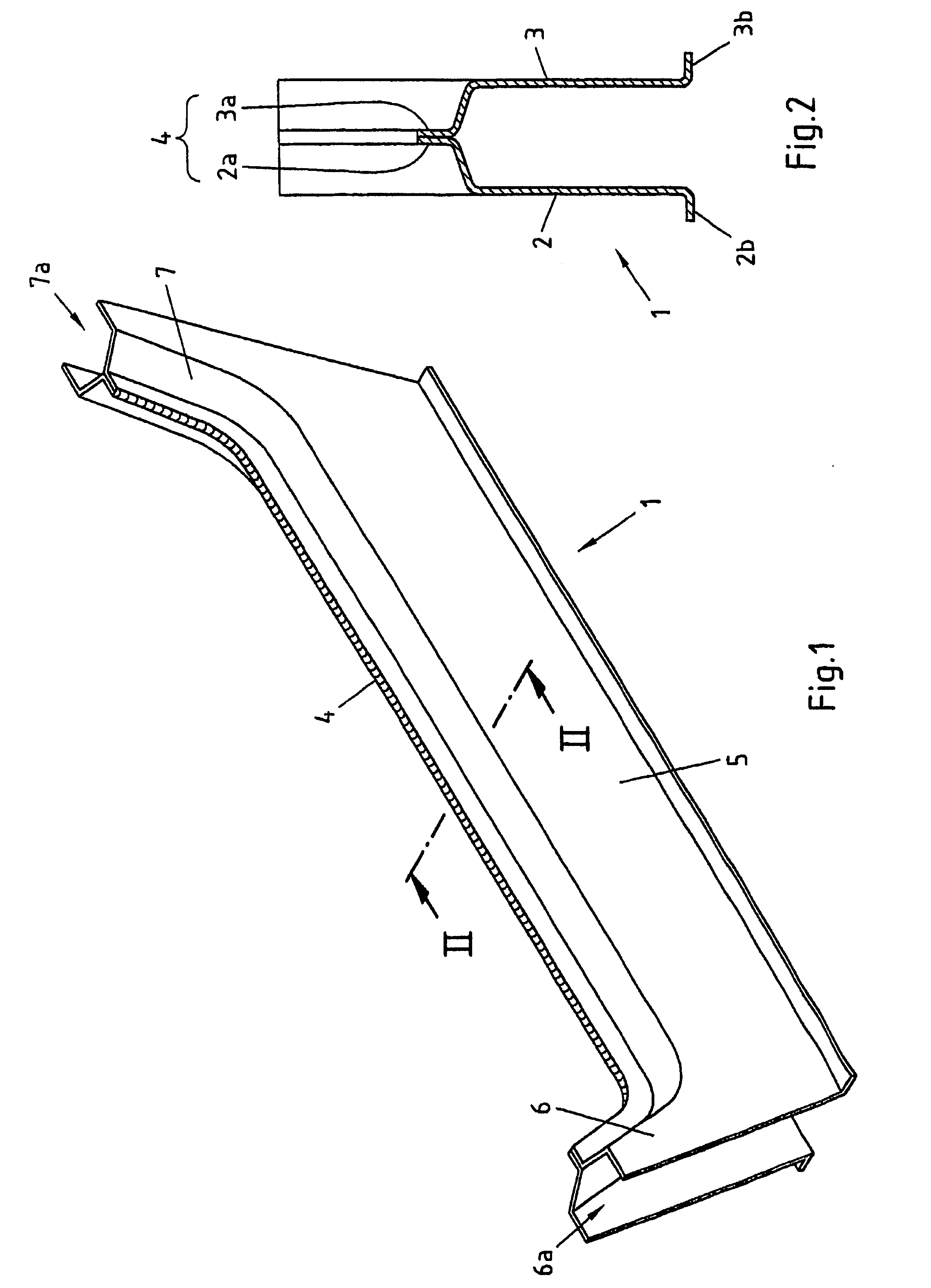
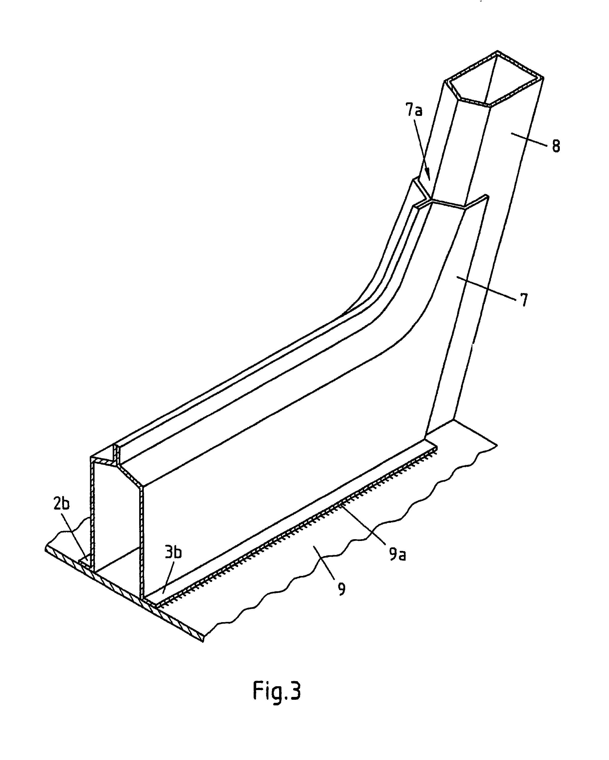
[0023]The reinforcing profile of the invention according to FIG. 1 is produced by hydroforming from a double blank 1 which, in turn, comprises two individual blanks 2, 3 welded at their edges 2a, 3a, preferably by laser beam welding, the reinforcing profile comprises a straight middle region (i.e., a vehicle transverse wall) 5, with a substantially U-shaped cross-section, which merges at its two ends into rounded corner reinforcements 6, 7. As a result, large open pillar connection zones 6a, 7a are formed which allow a uniform progression of force between two pillars, supported on the reinforcing profile, of a vehicle supporting frame. The edges 2a, 3a, welded at the end face, of the individual blanks jointly form an upper edge 4 in the reinforcing profile, which edge can be used as a flange for receiving seals or for mounting panelling components. At the base, the reinforcing profile also comprises edge regions 2b, 3b that are bent at a right angle and form flanges which can be eff...


PUM

PropertyMeasurementUnit
angleaaaaaaaaaa
rigidityaaaaaaaaaa
forceaaaaaaaaaa

Abstract

The invention relates to a reinforced section for a vehicle supporting frame, said section connecting two pillars (8) of the vehicle supporting frame, in particular the C-pillars or D-pillars at their bases in the form of a transversal wall, whose ends, which are configured as pillar connection zones (6a, 7a), extend onto the pillars (8) by means of rounded corner reinforcements (6, 7). The invention is characterised in that the reinforced section and the corner reinforcements (6, 7) are configured as a one-piece double shell consisting of two blanks (10) produced in an internal high-pressure forming process and welded together around their periphery.

Description

BACKGROUND OF THE INVENTION[0001]The invention relates to a reinforcing profile for a vehicle supporting frame, which connects at their bases two pillars of the vehicle supporting frame, in particular the C-pillars or D-pillars, as a vehicle transverse wall and at its ends formed as pillar connection zones merges via rounded corner reinforcements into the pillars.[0002]In modern vehicle construction a rigid vehicle structure is fundamentally important for the driving properties and the crash safety of a vehicle. A suitable measure for achieving increased rigidity is to additionally brace the vehicle supporting frame by fitting, oriented transversely to the direction of travel, reinforcing profiles as vehicle transverse walls.[0003]Reinforcing profiles of this type are known from practice. One such known reinforcing profile comprises a shell component constructed as a top hat profile which, in the fitted state, connects the supporting pillars at their bases and in the process is weld...

Claims


Application Information

Patent Timeline
Patent Type & Authority Patents(United States)
IPC IPC(8): B62D27/00B21D26/02B21D26/059B62D25/04B62D25/20
CPCB21D26/059B21D47/02B62D25/04B62D25/2036
Inventor GRUNEKLEE, AXELPATBERG, LOTHARWECKENMANN, ERNST
Owner THYSSENKRUPP STEEL EURO AG
Why Eureka
Try Eureka