Molded orthomode transducer

a transducer and orthomode technology, applied in waveguide horns, antennas, electrical devices, etc., can solve the problems of affecting the polarization performance of co-polarized, and presenting additional requirements for the feed system through dual-circular polarization

Active Publication Date: 2010-06-10
VIASAT INC
View PDF18 Cites 26 Cited by
  • Summary
  • Abstract
  • Description
  • Claims
  • Application Information

AI Technical Summary

Benefits of technology

[0011]In accordance with various aspects of the present invention, a method and system for a molded or cast dual-band four-port orthomode transducer (OMT) is presented. The OMT may be external to a transceiver housing or included as an integrated portion of the transceiver housing or a drop-in module. In an exemplary embodiment, a four-port OMT is formed from two pieces, the two pieces having a joint adjacent to or aligned to the axis of the common port. The two OMT pieces are joined and held together with a plurality of discrete fasteners such as screws or rivets.

Problems solved by technology

The use of dual-circular polarization may present additional requirements on the feed system due to the operational nature of circularly polarized signals.
The single or multiple reflected circular polarization signals in a constrained or guided RF signal path can have deleterious effects on system performance in systems that use polarization to isolate signals.
Multiple reflected signals may degrade the polarization performance of a co-polarized, or same sense polarization, signal through an interference effect.

Method used


Image

  • Molded orthomode transducer
  • Molded orthomode transducer
  • Molded orthomode transducer

Examples


second embodiment

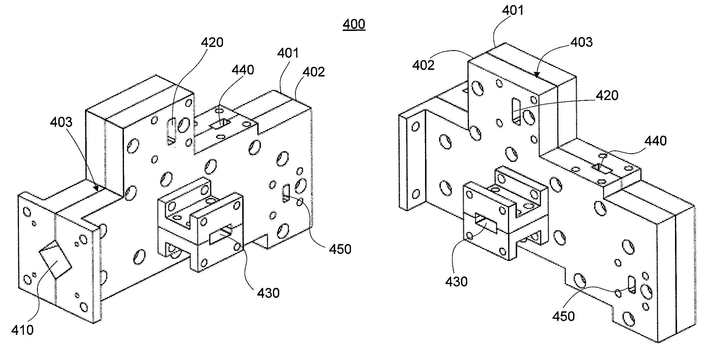
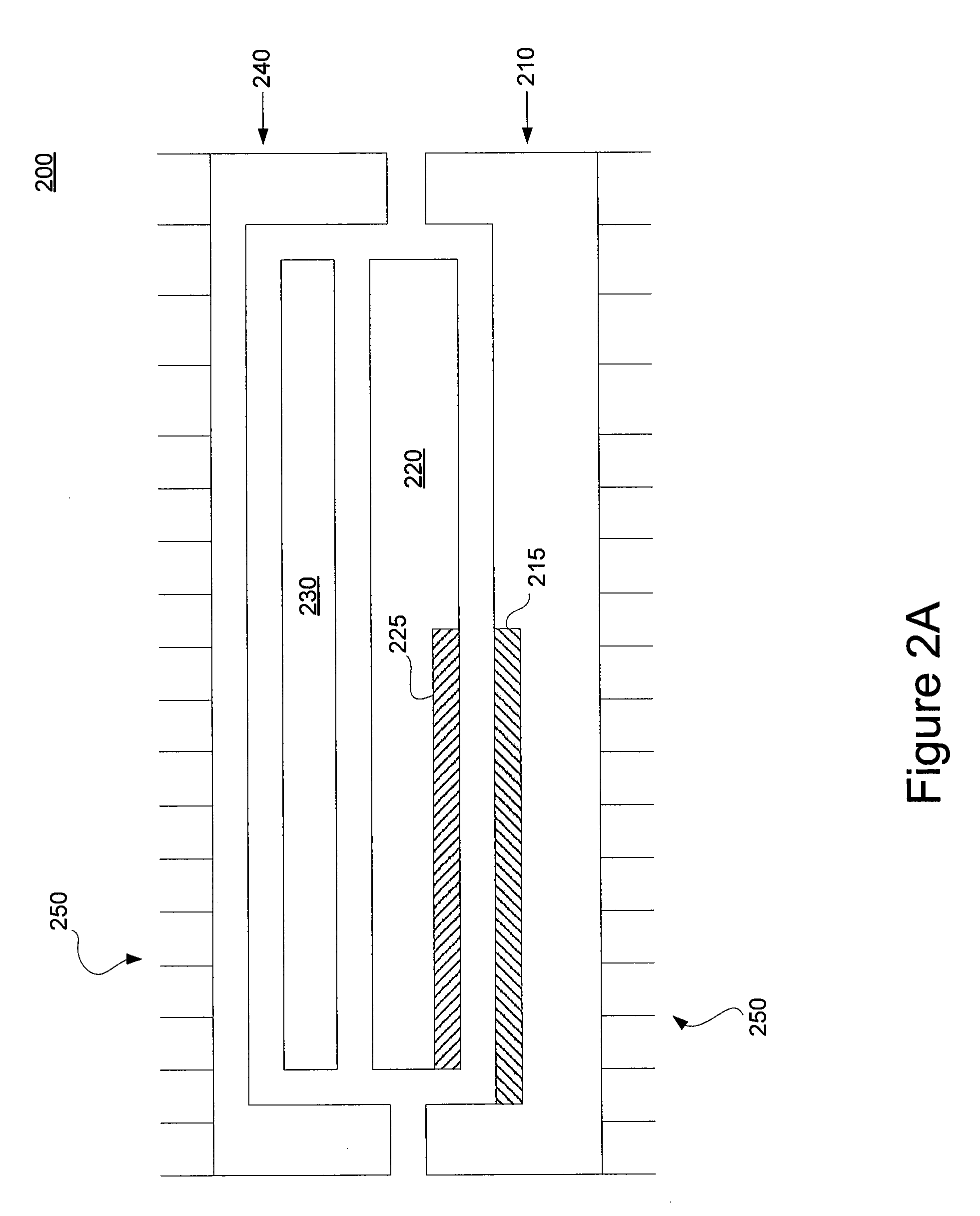
[0040]Various embodiments of the integrated split block OMT are contemplated, including different divisions of the OMT portions between first OMT portion 215 and second OMT portion 225. In one exemplary embodiment and with reference to FIG. 2B, first OMT portion 215 is cast with all, or substantially all, of a relief of the OMT, and second OMT portion 225 is flat, or substantially flat. By flat, it should be understood that second OMT portion 225 primarily forms a lid for the waveguide, but contains little more of the waveguide structure. In a second embodiment and with reference to FIG. 2C, first OMT portion 215 is flat, or substantially flat, and second OMT portion 225 is cast with all, or substantially all, of a relief of the OMT. Moreover, the OMT may be divided between the first and second OMT portion 215, 225 using any ratio or percentage of division. In an exemplary embodiment, first and second OMT portions 215, 225 are divided to be substantially equal and take into consider...

first embodiment

[0072]The common port of the OMT supports low loss signal transmission for both the first and second band segments. In a first embodiment, the first band segment is in the K-band which is a frequency range of about 18.3 to 20.2 GHz, resulting in a bandwidth of approximately 1900 MHz. The second band segment is the Ka-band which is a frequency range of about 28.1 to 30.0 GHz, resulting in a bandwidth of approximately 1900 MHz. These operational band segments are alternatively known as operational passbands. Moreover, a dual-band device operating over these two exemplary frequency ranges is also known as a K / Ka-Band device.

[0073]In a second embodiment, the first band segment can be K-band and the second band segment is the Q-band which is a frequency range of about 43.5 to 45.5 GHz, typically for military communications. In this embodiment, the K-band may be a frequency range of about 20.2 to 21.2 GHz. Furthermore, in a third exemplary embodiment a first band segment may be K-band, a ...


PUM


Abstract

In an exemplary embodiment, a dual-band four-port orthomode transducer (OMT) is molded or cast. The OMT may be external to a transceiver housing or included as an integrated portion of the transceiver housing or a drop-in module. In an exemplary embodiment, a four-port OMT is formed from two pieces, the two pieces having a joint adjacent to or aligned to the axis of the common port. In an exemplary embodiment, the OMT is substantially planar and formed of a split-block embodiment. The two OMT pieces are joined and held together with a plurality of discrete fasteners. Furthermore, the OMT is configured to switch polarizations. The polarization switching is initiated using a remote signal and can facilitate load balancing.

Description

CROSS-REFERENCE TO RELATED APPLICATIONS[0001]This application is a non-provisional of and claims priority to U.S. Provisional Patent Application No. 61 / 113,517, entitled “MOLDED ORTHOMODE TRANSDUCER” and filed Nov. 11, 2008, which is hereby incorporated by reference.FIELD OF INVENTION[0002]The application relates to systems, devices, and methods for transmitting and receiving signals in a satellite communications antenna system. More particularly, the application relates to a dual-band multi-port waveguide component used in an antenna having dual-linear or circular polarization and configuring the component for a molded or cast fabrication process of manufacture.BACKGROUND OF THE INVENTION[0003]With reference to prior art FIG. 1, in some ground based satellite communication antenna systems 100, a single antenna (feed horn) 120 is connected to a transceiver 101, where the transceiver combines the functionality of both a transmitter and a receiver. In these embodiments, typically, the...

Claims


Application Information

Patent Timeline
Patent Type & Authority Applications(United States)
IPC IPC(8): H01Q13/02H01P5/12H01P1/02H01Q13/00
CPCH01Q19/19H01P1/161
Inventor PAREKH, SHARAD VINODRAISKINNER, KEVIN MARKRUNYON, DONALD LAWSONKOKOTOFF, DAVID MARK
Owner VIASAT INC
Why Eureka
Try Eureka