Planar light-emitting device and liquid crystal display apparatus using the same

a light-emitting device and liquid crystal display technology, applied in the direction of illuminated signs, display means, instruments, etc., can solve the problems of undeflection of thin light-diffusing elements, increase in weight, and difficulty in solving them, so as to reduce the thickness and reduce the deflection of sheet-shaped light-diffusing elements. , the effect of preventing the deflection of sheet-shaped light-diffusing elements

Active Publication Date: 2010-06-10
NICHIA CORP
View PDF3 Cites 43 Cited by
  • Summary
  • Abstract
  • Description
  • Claims
  • Application Information

AI Technical Summary

Benefits of technology

[0010]It should be noted that the terms “upper edges”, “upward”, etc. as employed in the above are used only for explanatory purposes, and that these terms should not be construed as specifying a particular absolute positional relationship between the constituent elements of the planar light-emitting device. The sheet-shaped light-diffusing element is a sheet-shaped element having a light-diffusing function and includes those having various thicknesses. In this planar light-emitting device, the sheet-shaped light-diffusing element can be entirely supported by the upper edges of the partition, and thus the deflection of the sheet-shaped light-diffusing element can be prevented effectively. Accordingly, the sheet-shaped light-diffusing element can be reduced in thickness and increased in size, and the planar light-emitting device can be reduced in overall thickness and weight and increased in overall size, which contributes to the reduction in thickness and weight of a liquid crystal display apparatus using the planar light-emitting device, and which also contributes to the increase in size of the display apparatus. The sheet-shaped light-diffusing element may be supported by the upper edges of the partition through an optical sheet of high light transmittance placed on the partition upper edges. In this planar light-emitting device, the side surfaces of the partition reflect light from the light sources, thus enabling the light from the light sources to be used efficiently. The light sources set in the enclosed spaces, respectively, can be controlled independently of one another, which facilitates local dimming control. The local dimming control can be further facilitated by arranging the enclosed spaces in a matrix.
[0011]Specifically, the upper edges of the partition may be disposed in a plane parallel to the upper surface of the reflector. With this arrangement, the sheet-shaped light-diffusing element can be supported by the whole of the upper edges of the partition, and the deflection of the sheet-shaped light-diffusing element can be further reduced.
[0012]The planar light-emitting device may have a plurality of mutually spaced projections formed on the u...

Problems solved by technology

In this regard, there are some problems to be solved.
A backlight unit using a lightguide plate needs to install a large-sized lightguide plate or a plurality of lightguide plates in juxtaposed relation, resulting in an increase in weight.
Therefore, the thin l...

Method used


Image

  • Planar light-emitting device and liquid crystal display apparatus using the same
  • Planar light-emitting device and liquid crystal display apparatus using the same
  • Planar light-emitting device and liquid crystal display apparatus using the same

Examples


first embodiment

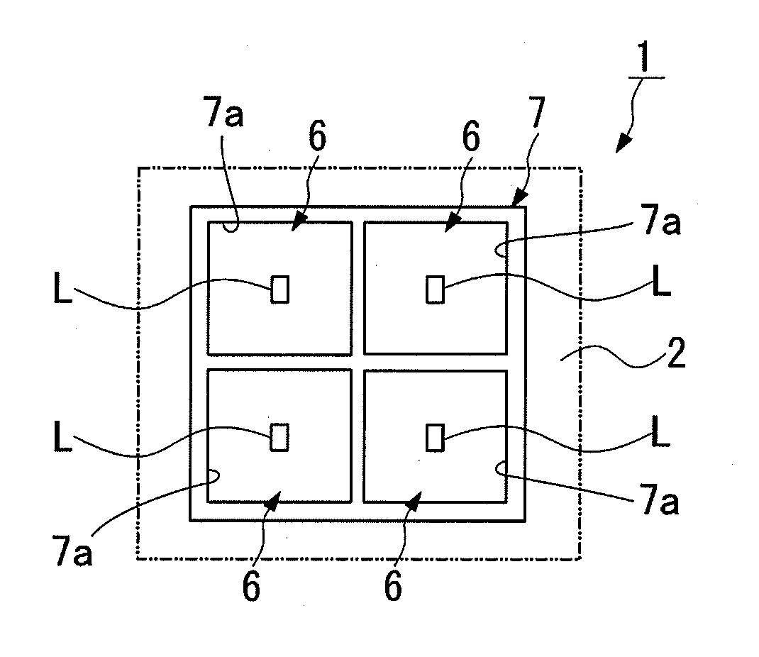
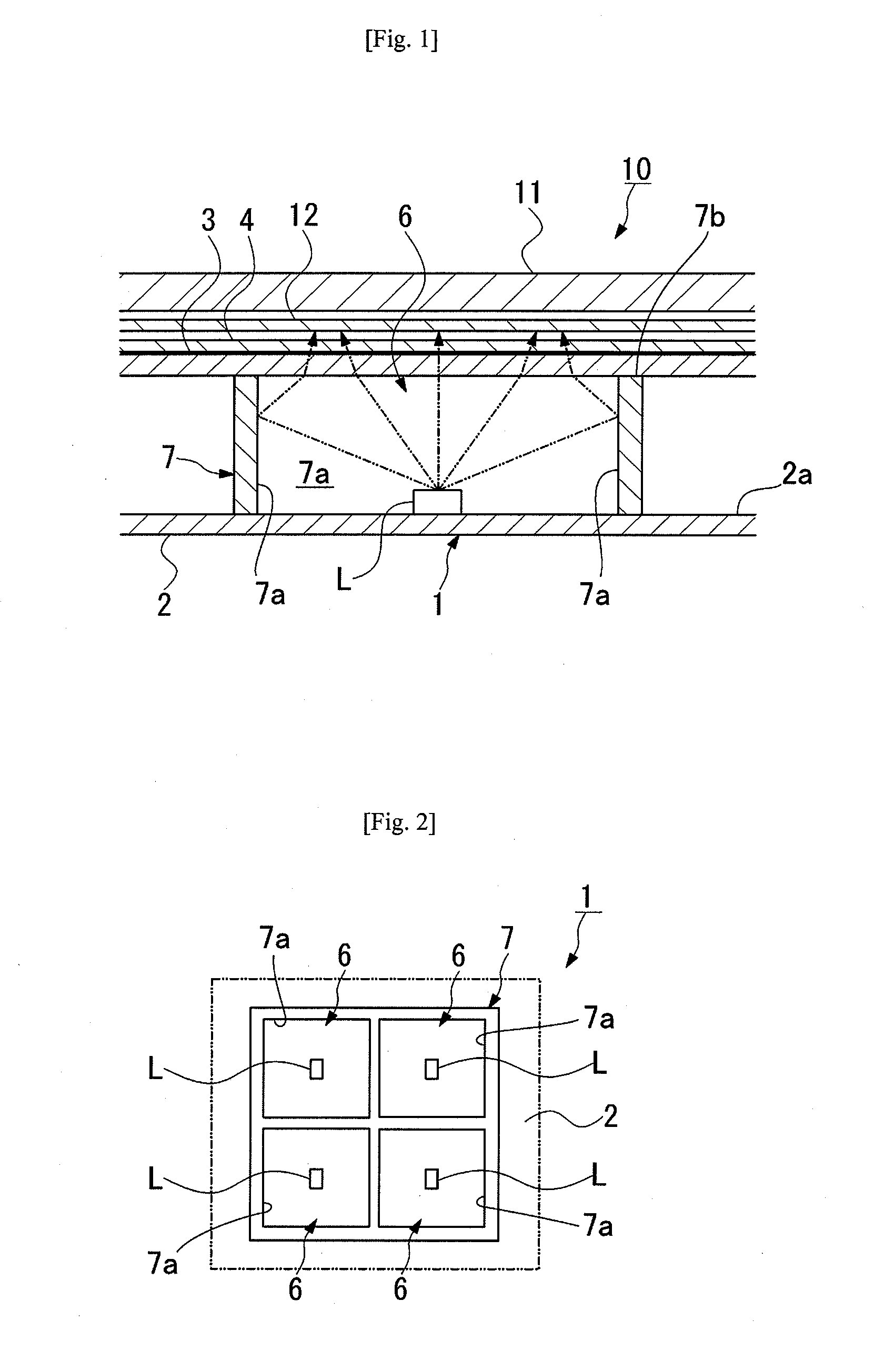
[0028]FIGS. 1 and 2 show a planar light-emitting device 1 according to the present invention. The planar light-emitting device 1 has a reflector 2 having an upper surface 2a serving as a light-reflecting surface and a partition 7 installed on the reflector 2 to extend upward to partition the space over the upper surface 2a of the reflector 2 into a plurality of enclosed spaces 6. Side surfaces 7a of the partition 7 that define the enclosed spaces 6 are light-reflecting surfaces. The planar light-emitting device 1 further has light sources L disposed on the upper surface 2a of the reflector 2 at the respective centers of the enclosed spaces 6, and a stack of sheet-shaped light-diffusing elements 3 and 4 supported on the upper edges 7b of the partition 7 to transmit and diffuse light from the light sources L upward.

[0029]In the illustrated example, the partition 7 is formed as a single member having a lattice structure by using a white resin having light-reflecting properties, and the...

second embodiment

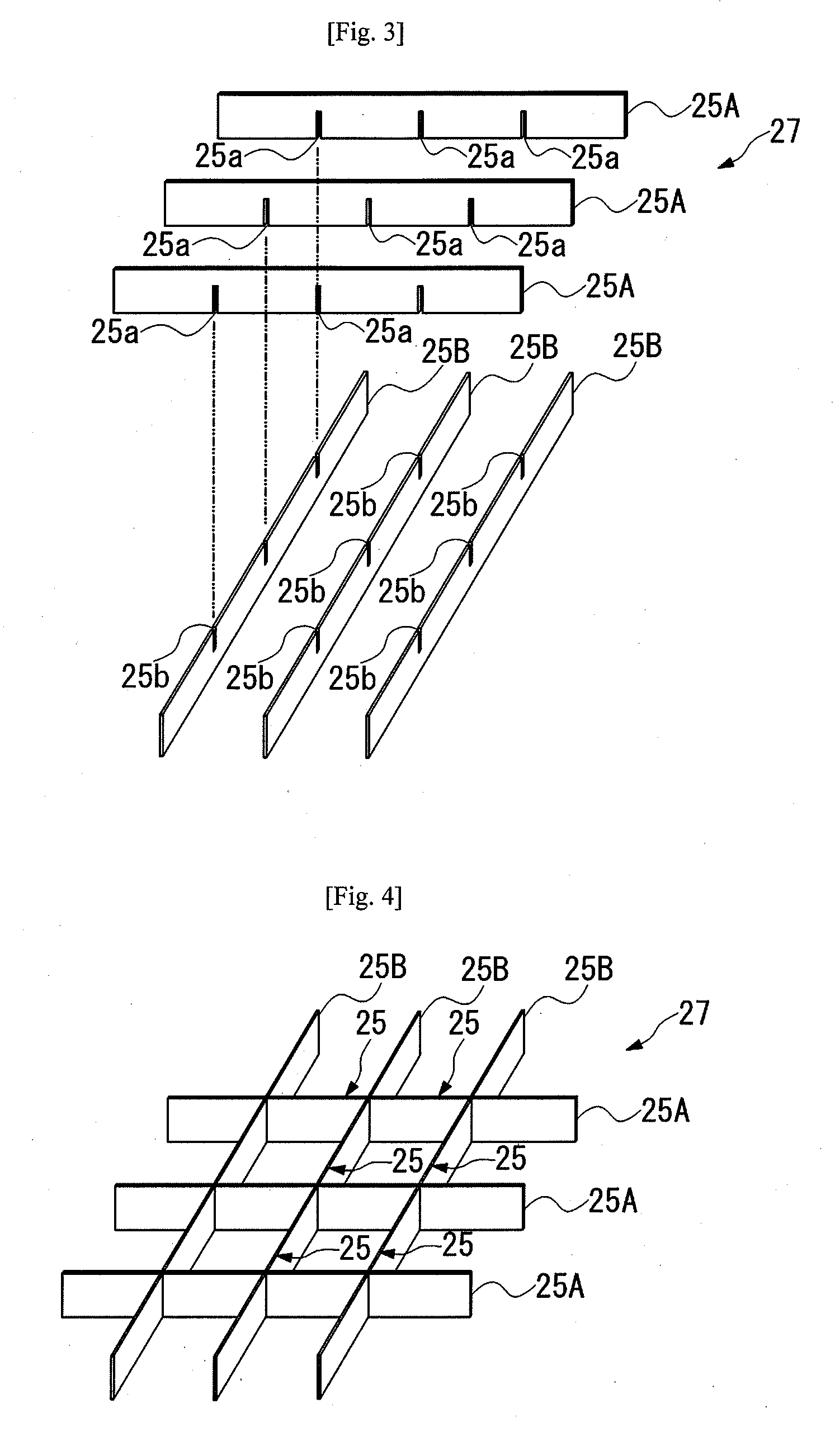
[0041]FIGS. 3 to 5 show a partition 27 according to the present invention. The partition 27 is formed by combining together a plurality of rectangular partition segments 25A and 25B in a matrix.

[0042]The rectangular partition segments 25A and 25B intersecting one another have a plurality of notches 25a and 25b, respectively, formed at a predetermined regular spacing. The notches 25a and 25b extend perpendicular to the longitudinal direction of the partition segments 25A and 25B. The partition segments 25A and 25B are inserted into one another's notches 25b and 25a and thus assembled in a lattice configuration. In the assembled state, the tops and bottoms of the partition segments 25A and 25B are flush with one another, respectively. Accordingly, the assembled partition 27 has a uniform height throughout. Thus, a partition of desired size can be formed easily by preparing a plurality of rectangular partition segments 25A and 25B of necessary size. The partition segments 25A and 25B a...


PUM


Abstract

A planar light-emitting device enabling reduction in the deflection of a sheet-shaped light-diffusing element includes a reflector having an upper surface serving as a light-reflecting surface, a partition provided on the reflector to extend upward to form a plurality of enclosed spaces over the upper surface of the reflector, light sources disposed in the enclosed spaces, respectively, and at least one sheet-shaped light-diffusing element supported on the upper edges of the partition to transmit and diffuse light from the light sources upward. The side surfaces of the partition that define the enclosed spaces are light-reflecting surfaces.

Description

[0001]This application claims priority under 35 U.S.C. Section 119 to Japanese Patent Application No. 2008-310820 filed on Dec. 5, 2008, the entire content of which is hereby incorporated by reference.BACKGROUND OF THE INVENTION[0002]1. Field of the Invention[0003]The present invention relates to a planar light-emitting device that illuminates a liquid crystal display panel or the like. The present invention also relates to a liquid crystal display apparatus using such a planar light-emitting device.[0004]2. Description of the Related Arts[0005]Liquid crystal display apparatuses for image display are widely used as the large-sized displays of flat-screen television systems and monitors, etc. These liquid crystal display apparatuses employ a backlight unit that applies illuminating light to a liquid crystal display panel from the back to enhance the luminance of the display screen. One type of such a backlight unit, for example, has a lightguide plate and a light source comprising, f...

Claims


Application Information

Patent Timeline
IPC IPC(8): G02F1/1335G02F1/13357
CPCG02F1/133605
Inventor OGIHARA, TAKESHIOKUWAKI, DAISAKUYASUHARA, MAKOTOKUMASAKA, TAKU
Owner NICHIA CORP
Why Eureka
Try Eureka