Digital signal encoding and decoding device and method

Active Publication Date: 2010-06-10
PANASONIC CORP
View PDF6 Cites 48 Cited by
  • Summary
  • Abstract
  • Description
  • Claims
  • Application Information

AI Technical Summary

Benefits of technology

[0053]The digital signal compression encoding and decoding device and the method of the present invention has no need to provide a table for encoding and decoding, an

Problems solved by technology

However, the processing from the RAW data to the data (compressed data) of the compressed data format is a time-consuming processing compared to the processing of reading out the accumulated charges of the pixel and temporarily storing it as the RAW data.
Therefore, when the storage capacity of the SDRAM is limited to a degree being same as that of a conventional product, th

Method used


Image

  • Digital signal encoding and decoding device and method
  • Digital signal encoding and decoding device and method
  • Digital signal encoding and decoding device and method

Examples


embodiment 1

[0118]

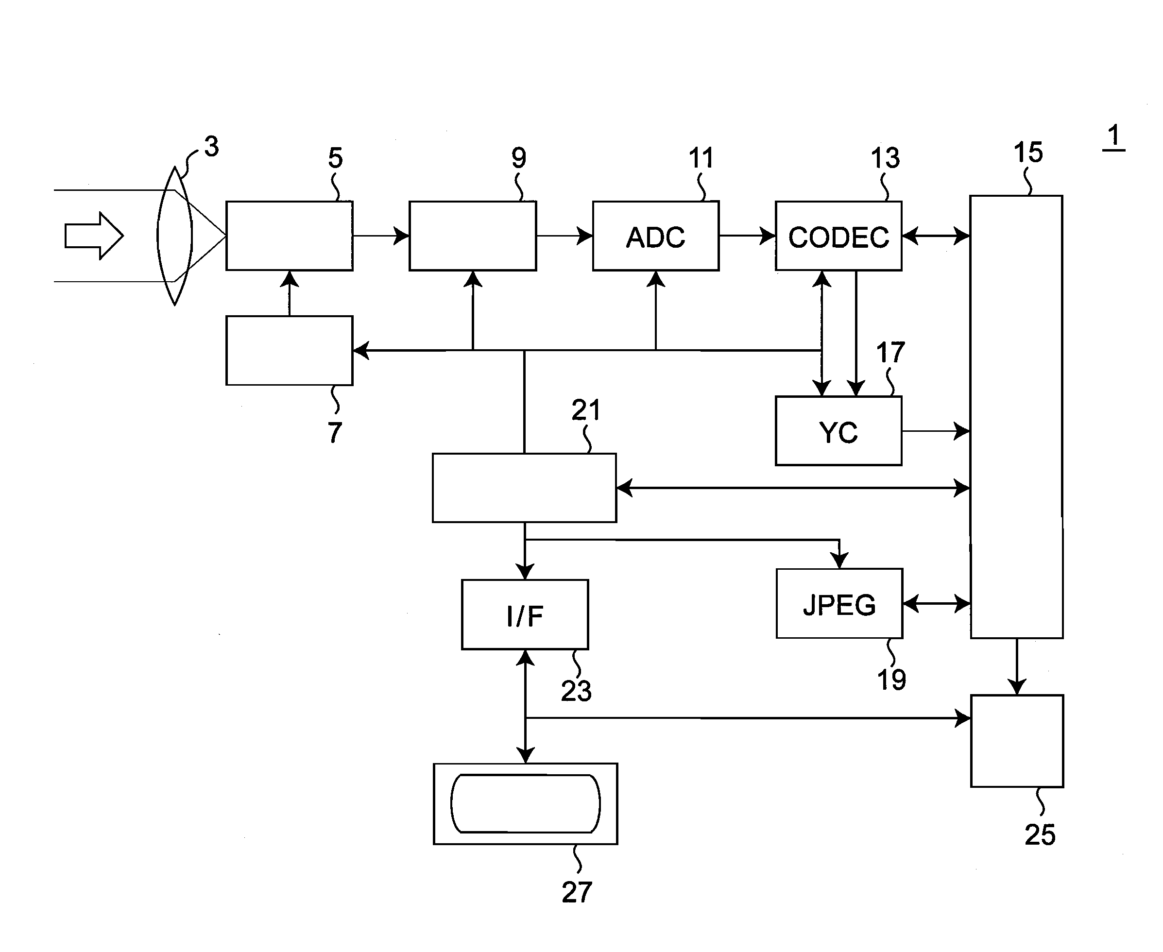
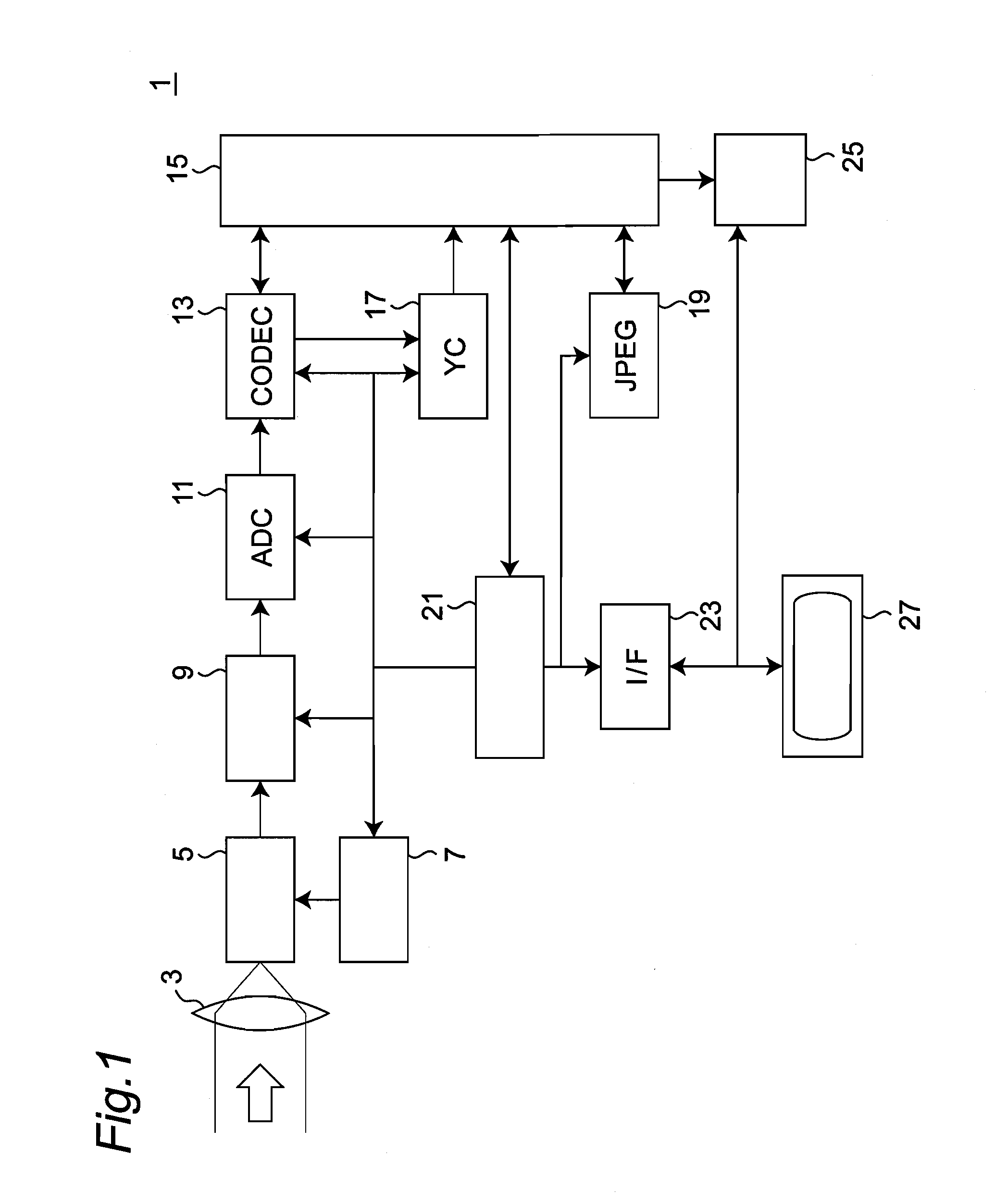
[0119]FIG. 1 is a block diagram of a digital still camera (DSC) 1 on which a digital signal compression encoding / decoding device (CODEC) 13 according to the present invention is mounted. Light incident to a lens 3 from an object being not shown is collected by the lens 3, and an image thereof is formed in a light receiving unit being not shown of an image pickup element 5. The image pickup element 5 is a CCD type imaging element. A pixel being not shown of the image pickup element 5 accumulates charges according to amount of the incident light. An image pickup element drive unit 7 outputs the accumulated charges as an analog pixel signal at a predetermined timing, and the signal is sent to a signal pre-processing unit 9. The signal pre-processing unit 9 applies pre-processing to the analog pixel signal, and sends the analog pixel signal to an analog / digital conversion unit 11. The analog / digital conversion unit (ADC) 11 converts the analog pixel signal into a digital pixel sig...

embodiment 2

[0206]

[0207]This embodiment provides a digital still camera (DSC) provided with a CODEC 113 having error feedback processing for reducing an error. This error often occurs in the quantization of the pixel value data by the CODEC (a difference between the pixel value data and the decoded pixel value data obtained through applying compression encoding processing to the pixel value data and further applying the decoding processing to the encoded pixel value data).

[0208]The DSC of this embodiment is similar to the DSC 1 according to the first embodiment except for the processing by the CODEC 113. According to FIG. 1, it is appropriate to consider that the CODEC 113 as will be explained hereunder is mounted on the DSC of this embodiment instead of the CODEC 13. Here, the configuration and processing of the CODEC 113 will be explained. A part not described in particular may be the same as that of the first embodiment.

[0209]FIG. 9 is a block diagram of the CODEC 113 according to this embod...

embodiment 3

[0219]

[0220]This embodiment provides a digital still camera (DSC) of which CODEC is capable of changing and optimizing the bit length of the compressed encoded pixel value data (the number of bits of the compressed encoded pixel value data), which is the compression encoding value of the pixel value data, according to the characteristic of an object which is actually imaged. The present embodiment provides the CODEC 213 having further higher compression efficiency. The DSC of this embodiment is similar to the DSC of the first and second embodiments, except for the processing in the CODEC 213. According to FIG. 1, it is appropriate to consider that the CODEC 213 as will be explained hereunder is mounted on the DSC of this embodiment instead of the CODEC 13. Here, the configuration and processing of the CODEC 213 will be explained. A part not described in particular may be the same as that of the first embodiment. The CODEC 213 of the present embodiment performs an optimal bit length ...


PUM


Abstract

An encoding device includes: a difference generation unit for obtaining a first pixel difference value as a difference value between a first pixel value and a pixel value of a pixel having the same color as the first pixel positioned in the vicinity of the first pixel; a quantization width decision unit for deciding a quantization width in data generation by quantizing the first and the second pixel value according to the number of digits of an unsigned integer binary value of the first pixel difference value and the number of digits of an unsigned integer binary value of the second pixel difference value generated in the difference generation unit for the second pixel value of the second pixel; a quantization width information generation unit for generating quantization width information having a quantization width used for quantization/decoding of the first and the second pixel value; and a quantization unit for generating a first and a second compressed encoded pixel value of n-bit length.

Description

TECHNICAL FIELD [0001]The present invention relates to a compression encoding and decoding of digital data. Specifically, the present invention relates to a device and a method for compressing and encoding a pixel signal outputted by an image pickup element, and for decoding the compressed and encoded pixel signal.BACKGROUND ART [0002]The image pickup element which is mounted on a digital imaging apparatus such as a digital camera and a cellular phone with a built-in camera includes such as a charge coupled type image pickup element (a CCD type image pickup element) and a metal oxide semiconductor type image pickup element (a MOS type image pickup element). Further, the MOS type image pickup element includes a complementary metal oxide semiconductor type image pickup element (a CMOS type image pickup element), an N-channel metal oxide semiconductor type image pickup element (an NMOS type image pickup element), and the like. In recent years, there is a tendency that the number of pix...

Claims


Application Information

Patent Timeline
IPC IPC(8): G06K9/36G06T9/00H04N19/126H04N1/41H04N11/04H04N19/137H04N19/182H04N19/186H04N19/196H04N19/50H04N19/593
CPCH04N1/41H04N1/64H04N19/105H04N19/182H04N19/126H04N19/186H04N19/50H04N19/124H04N11/04
Inventor OKAMOTO, KAZUOJURI, TATSURO
Owner PANASONIC CORP
Why Eureka
Try Eureka