Image compression apparatus

a compression apparatus and image compression technology, applied in the direction of electrical apparatus, instruments, computing, etc., can solve the problems of uniform deformation, image quality is disadvantageous, and image data quality is greatly degraded, so as to improve the data compression rate of the image compression apparatus, and reduce the amount of data

Active Publication Date: 2009-12-01
TOA CORP
View PDF13 Cites 7 Cited by
  • Summary
  • Abstract
  • Description
  • Claims
  • Application Information

AI Technical Summary

Benefits of technology

[0021]According to the present invention, it is possible to improve the data compression rate of the image compression apparatus using the downsampling processing. In addition, it is possible to improve the data compression rate of the image compression apparatus that can use a general-purpose data compressor and a general-purpose data expander and that reduces the data amount while making a quality of an image different among regions. It is particularly possible to realize a high compression rate using the JPEG compressor and the JPEG expander.

Problems solved by technology

However, if a large data amount is reduced in the quantization processing, which is an irreversible processing, a quality of the restored image data is greatly degraded.
In addition, this quality degradation occurs throughout the image.
Due to this, even if an important region and an unimportant region are present in the image, the image quality is disadvantageously, uniformly degraded in the both regions.
Due to this, a general-purpose JPEG compression processor such as a JPEG chipset can not be employed as this data compression processor and the data compression processor is disadvantageously made expensive.

Method used


Image

  • Image compression apparatus
  • Image compression apparatus
  • Image compression apparatus

Examples


first embodiment

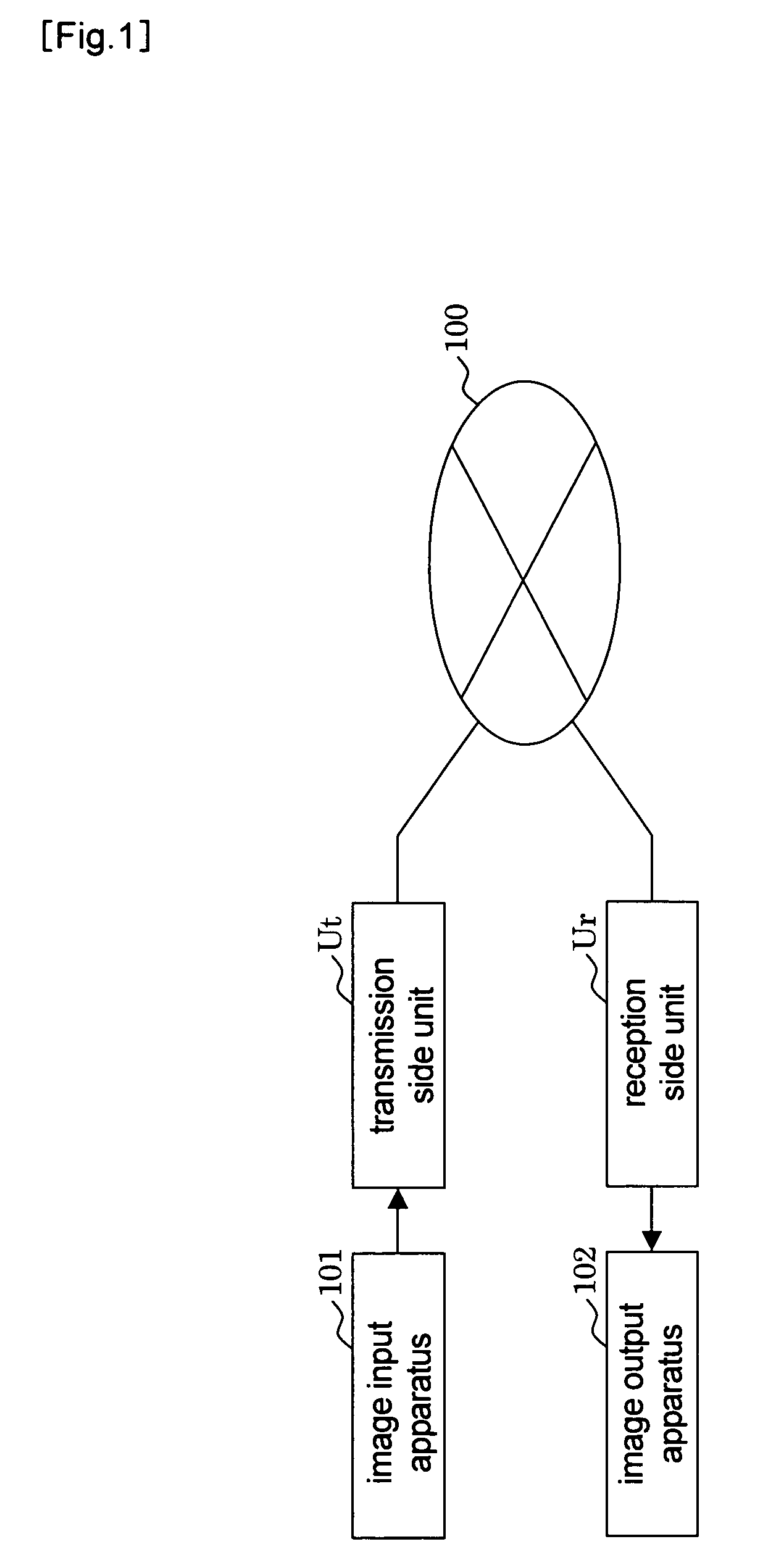
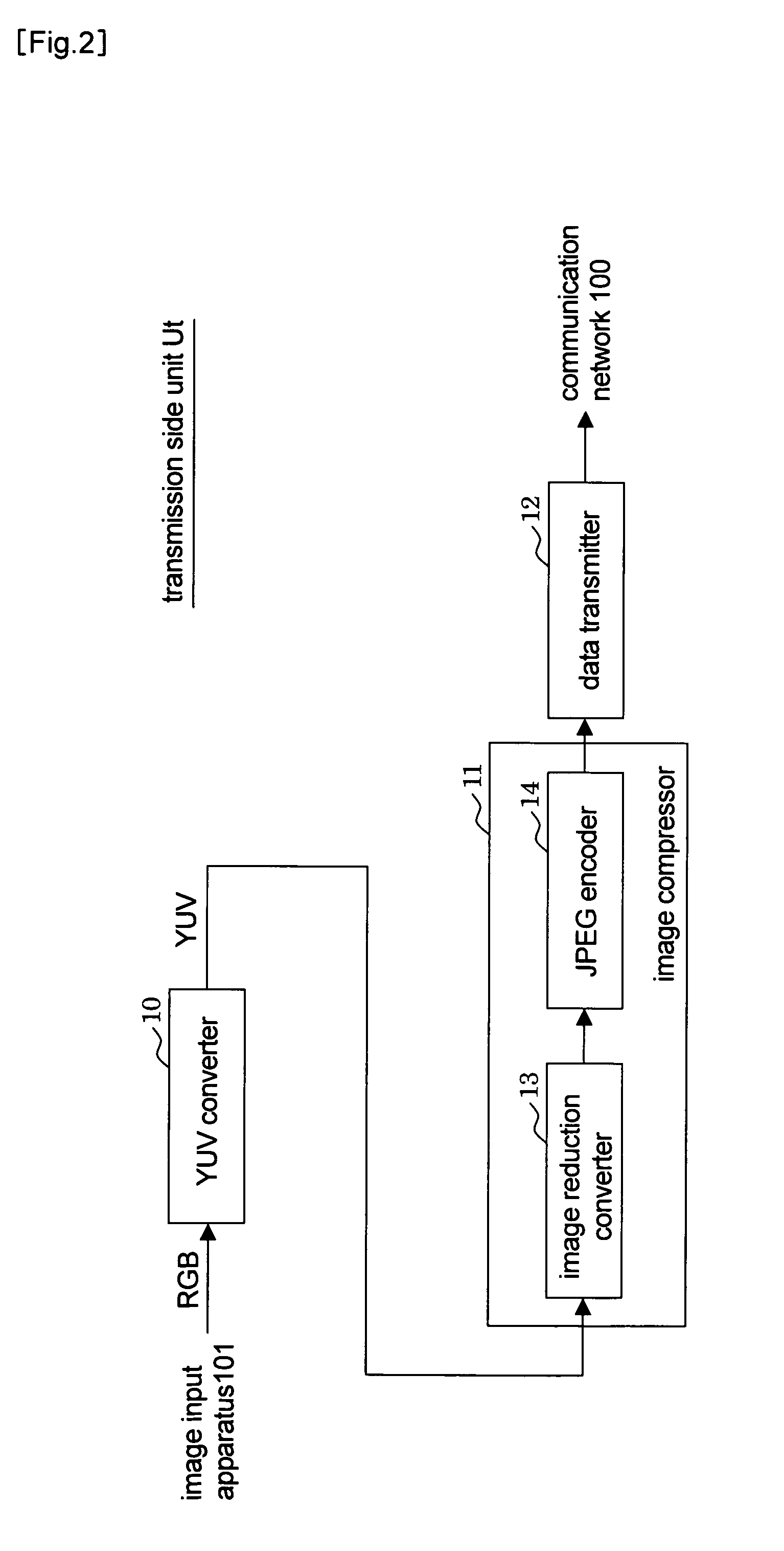
[0022]FIG. 1 is a block diagram of an example of a configuration of an image compression and expansion system according to the first embodiment of the present invention and shows an example of an image transmission system. This image transmission system includes a transmission side unit Ut and a reception side unit Ur connected to each other by a communication network 100 and can compress image data and transmit the compressed image data from the transmission side unit Ut to the reception side unit Ur. In this embodiment, image data of an image input apparatus 101 connected to the transmission side unit Ut is transmitted to an image output apparatus 102 connected to the reception side unit Ur.

[0023]The communication network 100, which is constituted by a wired or wireless communication line for transmitting digital data, includes an exchange unit and / or a repeater unit if it is necessary to do so. For example, a packet communication network such as Ethernet®, the Internet or ATM (As...

second embodiment

[0080]In the image compression and expansion system according to the first embodiment, the arrangement restoring unit 241 of the image enlargement converter 24 discriminates whether the unreduced data or the reduced data is arranged in each DS region based on the position of the fill region present in the DS region. Due to this, if a part of the unreduced data or the reduced data coincides with the fill data, there is a probability that the arrangement restoring unit 241 makes an erroneous discrimination. In the present embodiment, an image compression and expansion system capable of preventing such erroneous discrimination will be described.

[0081]Normally, a quantization error occurs to the image data compressed by the JPEG encoder 14. Namely, if an arbitrary value is adopted as the fill data, the fill data inserted into the image data by the image reduction converter 13 may possibly be changed to different data by the time the image data is input to the image enlargement converter...

third embodiment

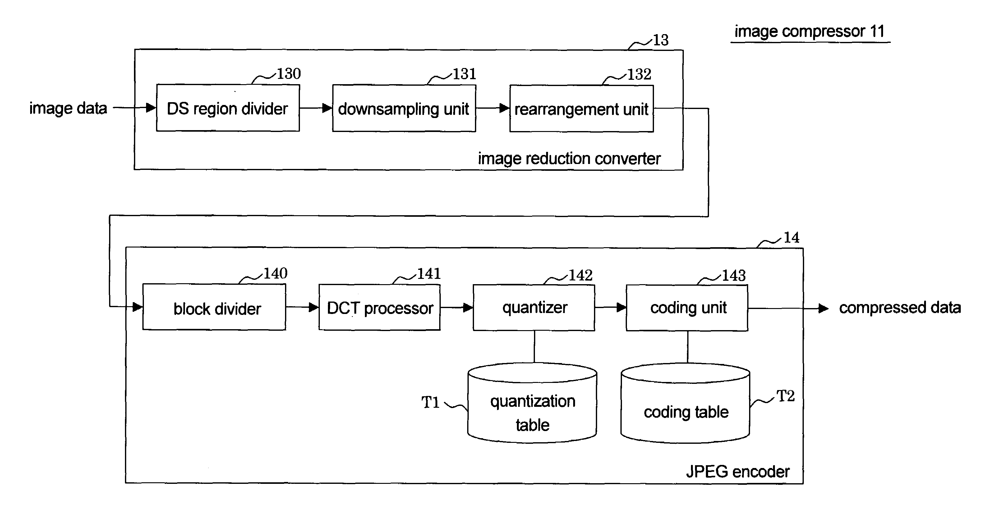
[0095]In the first embodiment, the instance of dividing the entire image into the DS regions at the equal size has been described. In the present embodiment, by contrast, an instance of dividing the entire image into DS regions at different sizes and using different reduction rates in downsampling will be described.

[0096]FIGS. 12(a) to 12(c) show an example of an operation performed by an image compression and expansion system according to the third embodiment of the present invention.

[0097]FIG. 12(a) shows a state in which a DS region divider 130 divides the image into DS regions. The DS region divider 130 divides the entire image into DS regions with a mixture of two or more different sizes. In the present embodiment, large DS regions each at a size of 32×32 pixels and small DS regions each at a size of 16×16 pixels are mixed together. On this occasion, the DS region divider 130 divides the image so that the important region is included in small DS regions. In addition, the DS reg...


PUM


Abstract

To improve the data compression ratio in the data compression / decompression method utilizing the down-sampling process. Image data in a DS area division unit (130) is divided into a plenty of DS areas and DS areas which are not important are converted into contracted data of the block size by down-sampling in a down-sampling unit (131). A relocation unit (132) allocates two or more contracted data in one DS area, inserts file data into the other portion in the DS area, and removes the DS area where no contracted data is allocated, thereby reducing the entire image size. The image data thus contracted is inputted into a JPEG encoder (14) and subjected to a DCT process and a quantization process for each block. When performing restoration, decompression is performed by the JPEG decoder and the original location is restored. As for the contracted data, interpolation is performed to restore the image data.

Description

[0001]This application is a 371 of PCT / JP05 / 02259 filed Feb. 15, 2005.TECHNICAL FIELD OF THE INVENTION[0002]The present invention relates to an image compressing and / or expanding method, an image compression apparatus, and an image expansion apparatus. More specifically, the present invention relates to an improvement of an image compressing and / or expanding method such as JPEG compressing and / or expanding method for performing orthogonal transform and quantization on image data for every block region obtained by dividing the image data into a plurality of block regions.BACKGROUND ART[0003]As methods for compressing and / or expanding image data constituted by a still image, there are widely known JPEG (Joint Photographic Expert Group) standards standardized according to CCITT (International Telegraph and Telephone Consultative Committee) and ISO (International Standards Organization). In the JPEG standards, an image data compressing method performed by dividing a frame image into a p...

Claims


Application Information

Patent Timeline
Patent Type & Authority Patents(United States)
IPC IPC(8): G06K9/36G06K9/46H04N1/41
CPCH04N19/124H04N19/17H04N19/59H04N19/117H04N19/14
Inventor TABUCHI, HIROSHITAGUCHI, AKIRASHIMAUCHI, KAZUHIROMOROHASHI, TOSHIO
Owner TOA CORP
Why Eureka
Try Eureka