High bit rate bidirectional passive optical network, associated optical exchange and line termination device

a passive optical network and high bit rate technology, applied in the field of optical access networks, can solve the problems of access networks, electrical energy consumption, and networks that are costly for telecommunications operators

Active Publication Date: 2010-06-10
FRANCE TELECOM SA
View PDF4 Cites 18 Cited by
  • Summary
  • Abstract
  • Description
  • Claims
  • Application Information

AI Technical Summary

Benefits of technology

[0035]The benefit of the generation means according to the invention lies in the reuse of the downlink optical signal from the optical exchange in the line termination module in the subscriber's home to produce an uplink optical signal, by exploiting the constant amplitude of the downlink optical signal phase-modulated in NRZ-DPSK format. Such means are capable of remodulating the downlink optical signal, so as to avoid having to use an additional laser in the home of each customer of the PON network.
[003...

Problems solved by technology

Access networks are networks that are costly to the telecommunications operators because they are more often than not tree-structured networks serving numerous subscribers.
Such networks are equipped with numerous components that often consume electrical energy.
This limited range of the network results from the fact that, in the passive optical networks, the various optical components that are, for example, the optical couplers, the optical multiplexers or the optical fibers, bring about optical power losses in the signals passing through the network and that the transmitted signals cannot be amplified without constraints to compensate such losses.
Howeve...

Method used


Image

  • High bit rate bidirectional passive optical network, associated optical exchange and line termination device
  • High bit rate bidirectional passive optical network, associated optical exchange and line termination device
  • High bit rate bidirectional passive optical network, associated optical exchange and line termination device

Examples


first embodiment

[0084]In this first embodiment of a high bit rate, long haul passive optical network, the amplification means 15 and 31 transmit an amplification signal at a single wavelength, for example at 1450 nm for the downlink and uplink optical signals transmitted at the wavelength of 1550 nm.

second embodiment

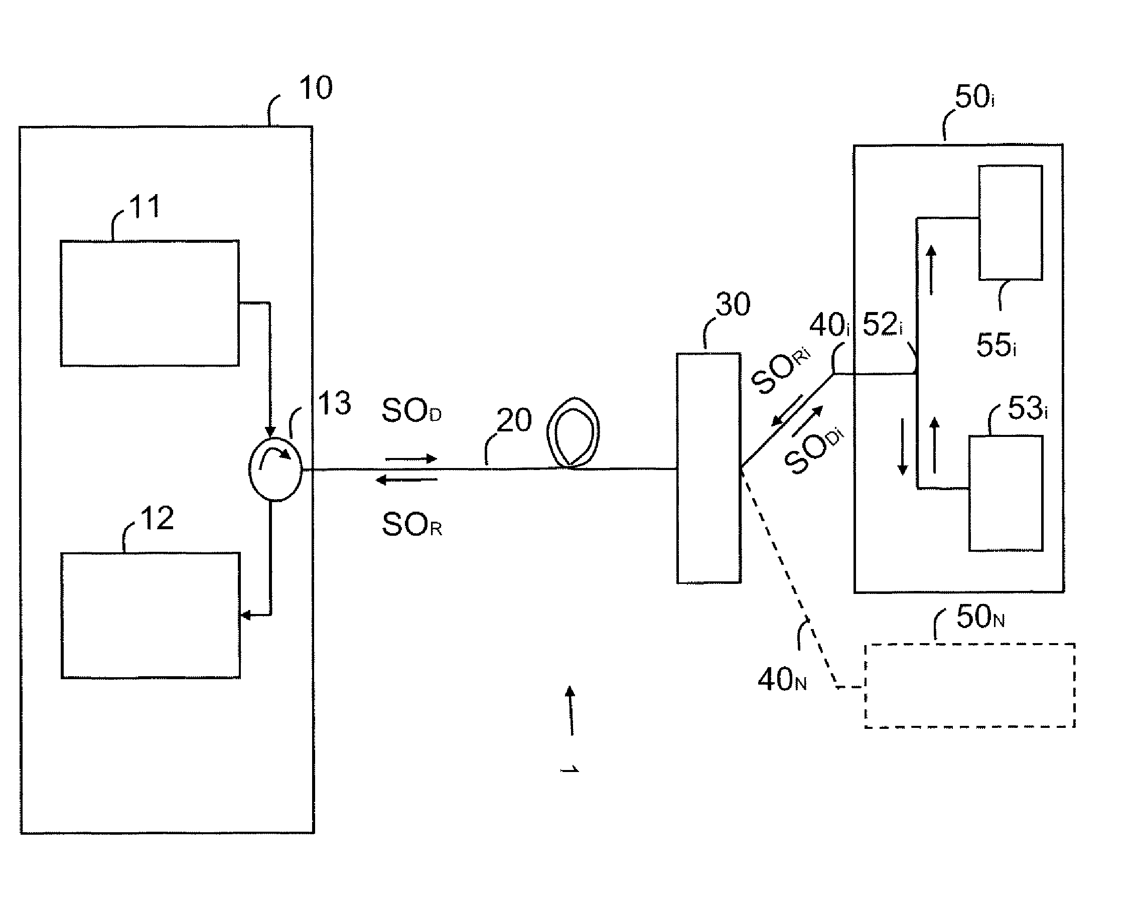
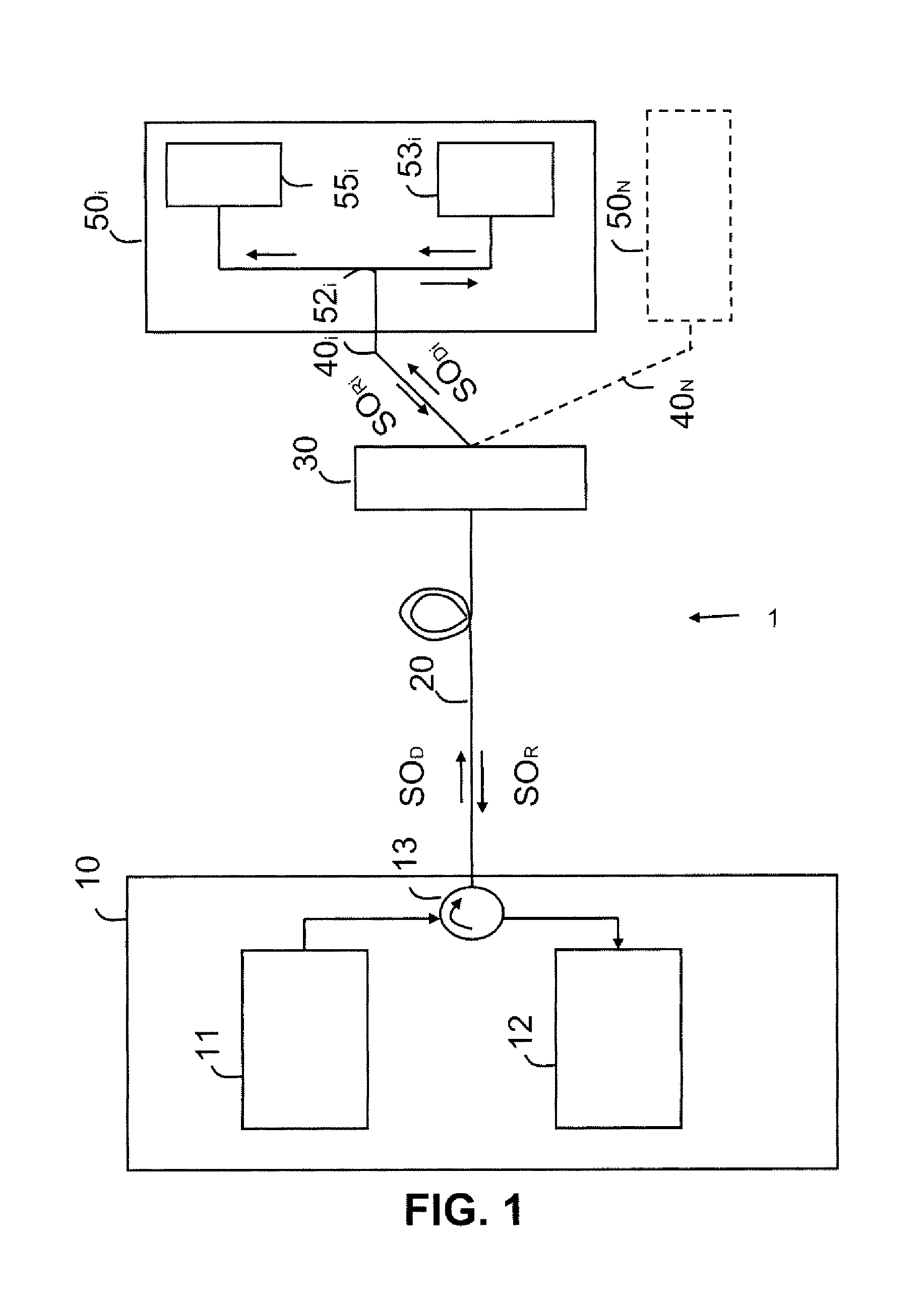
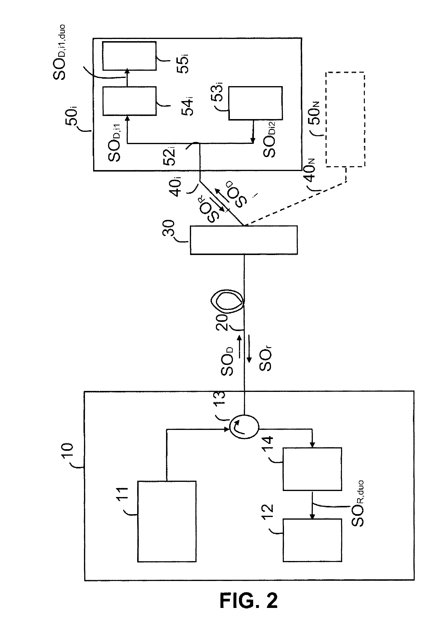
[0085]In a high bit rate, long haul passive optical network, the WDM technology is used, based on the distribution of the wavelength resources. In other words, a subscriber is allocated a wavelength. In this case, the line distribution element 30 is a 1-to-N optical multiplexer / demultiplexer which filters the downlink optical signal SOD and routes to a subscriber only the portion of this signal that concerns him and that, in the uplink direction, multiplexes the uplink signals transmitted, at different wavelengths, by the different line termination devices. Compared to the TDM passive network, the WDM access network is more costly, because it uses a greater number of wavelengths and a routing element. On the other hand, it is simpler to implement and offers subscribers greater security, because a wavelength is assigned to a subscriber and the optical demultiplexer attenuates the transmitted signal far less than the coupler does.

[0086]With a WDM access network, the amplification mean...


PUM


Abstract

The invention relates to a passive optical network comprising an optical exchange linked by at least one optical fiber to at least one line termination device of said network, able to transmit a downlink optical signal phase-modulated in NRZ-DPSK format and to receive an uplink optical signal.
According to the invention, said line termination device comprises means of converting the transmitted downlink optical signal phase-modulated in NRZ-DPSK format into an optical data signal amplitude-modulated in duobinary modulation format and means of generating an uplink optical signal phase-modulated in NRZ-DPSK format from the downlink optical signal phase-modulated in NRZ-DPSK format. The optical exchange is able to convert the uplink optical signal phase-modulated in NRZ-DPSK format into an optical data signal amplitude-modulated in duobinary modulation format.

Description

FIELD OF THE INVENTION[0001]The invention relates to the field of optical access networks and, more particularly, the field of passive optical access networks or PON (Passive Optical Networks).[0002]Access networks are networks that are costly to the telecommunications operators because they are more often than not tree-structured networks serving numerous subscribers. Such networks are equipped with numerous components that often consume electrical energy. In order to limit these operating costs while improving the quality of the services offered to the subscribers, the operators have developed passive optical access networks. All the components located in the network between the optical exchange and the user equipment are passive, that is to say that they do not need to be electrically powered to function.[0003]Such optical networks offer subscribers a high connection bit rate of the order of 2.5 Gbit / s (Gigabits per second). These bit rates make it possible to offer services such...

Claims


Application Information

Patent Timeline
IPC IPC(8): H04B10/20H04J14/00H04B10/2513H04B10/66
CPCH04B10/66H04B10/2513
Inventor PINCEMIN, ERWANGENAY, NAVEENA
Owner FRANCE TELECOM SA
Why Eureka
Try Eureka