Image forming apparatus

Active Publication Date: 2010-06-10
KONICA MINOLTA BUSINESS TECH INC
View PDF7 Cites 8 Cited by
  • Summary
  • Abstract
  • Description
  • Claims
  • Application Information

AI Technical Summary

Benefits of technology

[0011]An object of the present invention is to provide an image forming apparatus al

Problems solved by technology

In each of the image forming apparatuses described in Documents 1, 2, accuracy in the gap is not necessarily sufficient between the photoreceptor drum and the developing roller due to the following reasons.
In the image forming apparatus described in Document 1, the developing unit is “displaced” on the rail, which changes the biasing force provided from the spring member, thus resulting in a less accurate gap be

Method used


Image

  • Image forming apparatus
  • Image forming apparatus
  • Image forming apparatus

Examples


Embodiment Construction

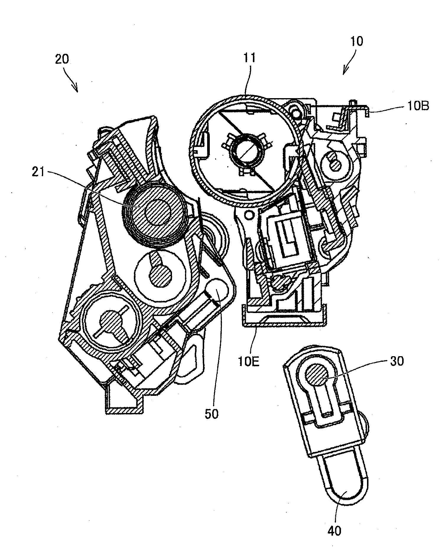
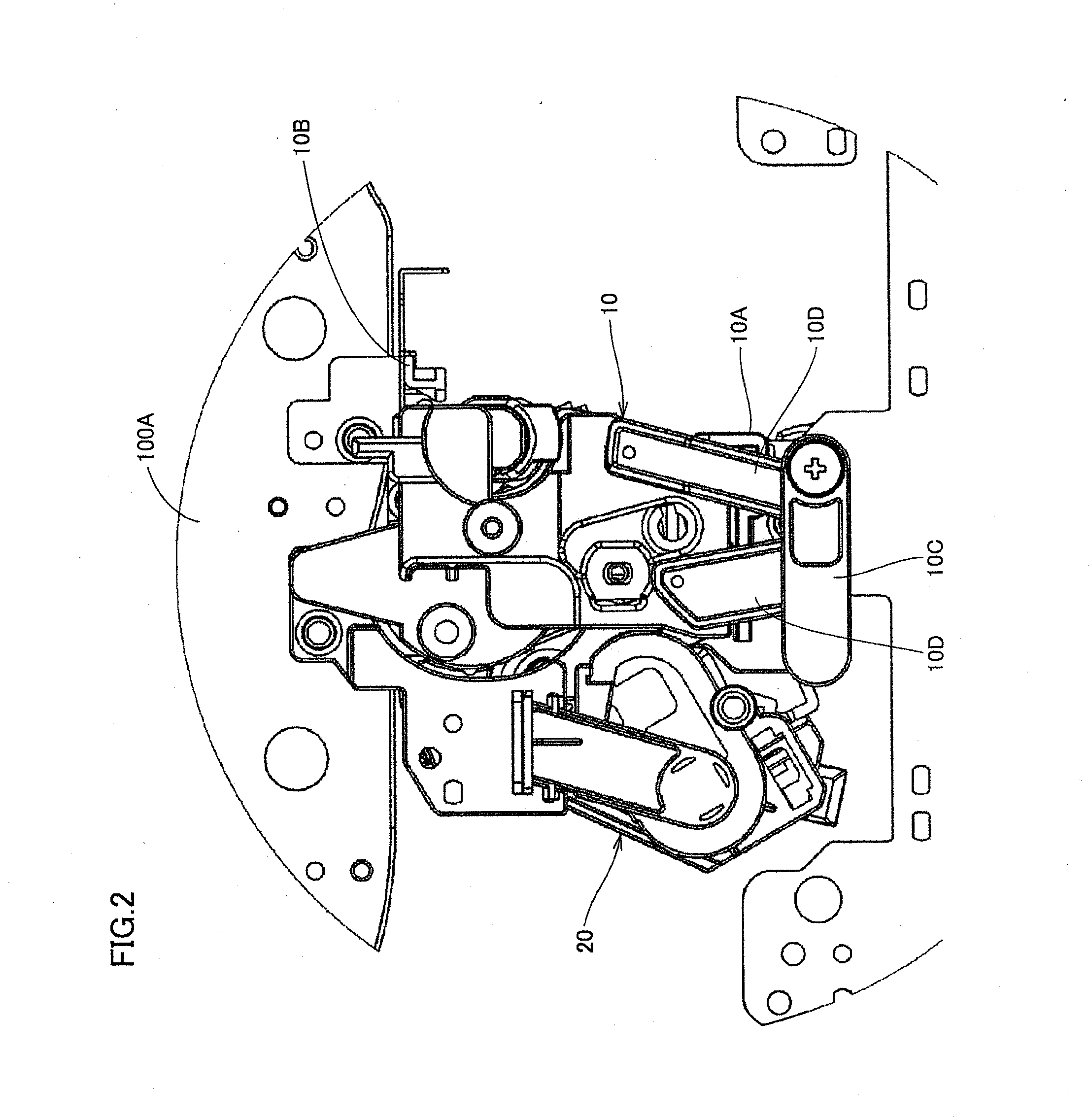
[0035]Embodiment of the present invention will be described below. It should be noted that the same or equivalent portions are given the same reference characters and may not be described repeatedly.

[0036]It should be also noted that the scope of the present invention is not necessarily limited to the number, amount, and the like described in the embodiment described below, unless otherwise noted. Furthermore, in the embodiment below, each component is not necessarily required in the present invention unless otherwise noted.

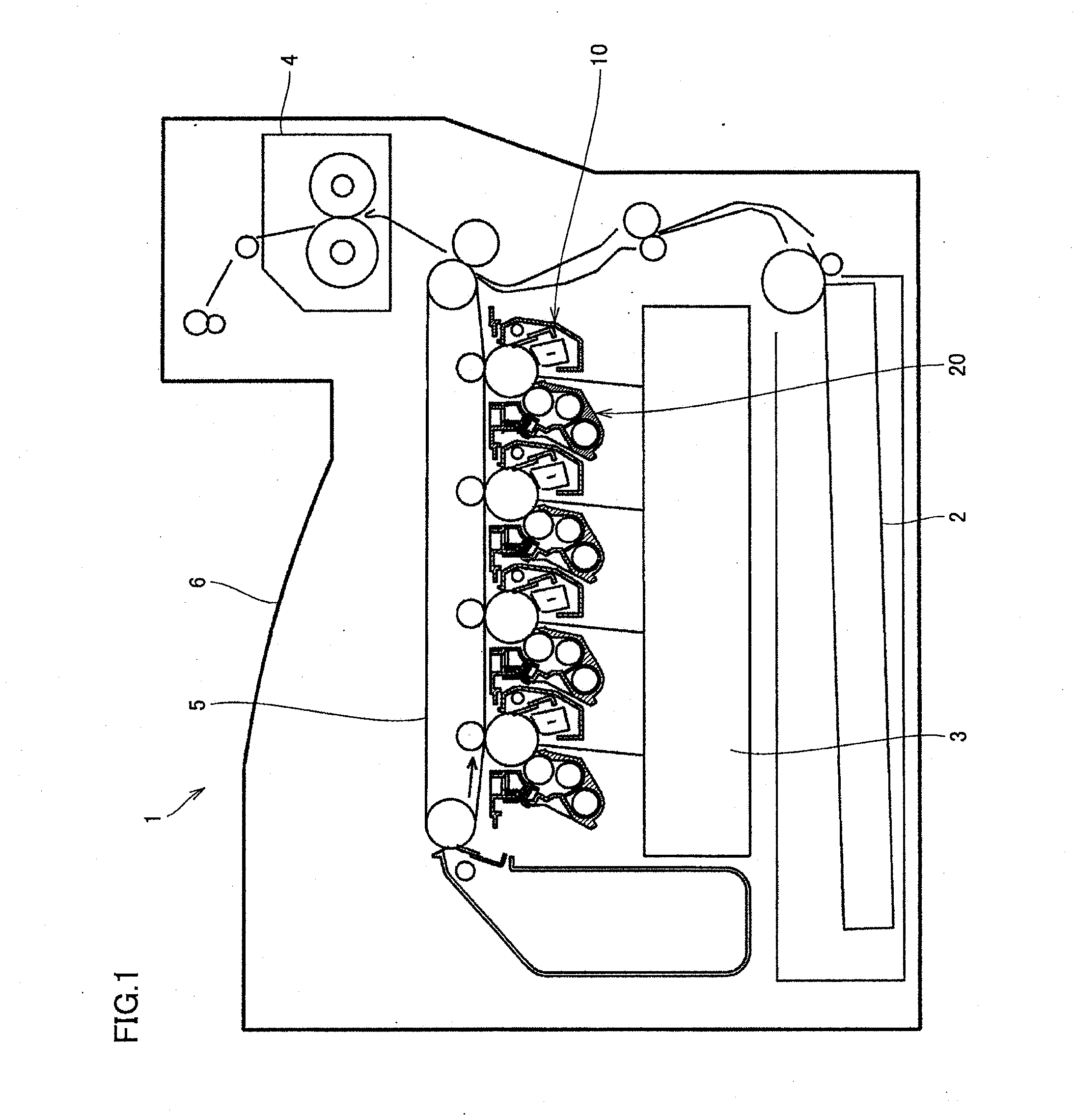
[0037]FIG. 1 is a diagram showing the entire configuration of an image forming apparatus according to one embodiment of the present invention. Referring to FIG. 1, image forming apparatus 1 corresponds to, for example, a copier, a printer, a facsimile machine and the like, and serves to form a predetermined image on a sheet of paper 2.

[0038]Image forming apparatus 1 includes an exposure unit 3, a fixing unit 4, a transfer belt 5, and a paper discharge tray 6. Fur...


PUM


Abstract

An image forming apparatus includes: a photoreceptor unit having a photoreceptor drum on which an electrostatic latent image is formed; a developing unit for developing the electrostatic latent image formed on the photoreceptor drum; a developing unit supporting shaft for rotatably supporting the developing unit; a pressing lever for pushing and rotating the developing unit to press the developing unit against the photoreceptor unit; a rotatable pressing lever shaft for supporting the pressing lever; and a holding member for holding the developing unit supporting shaft and the pressing lever shaft to maintain a fixed distance between the developing unit supporting shaft and the pressing lever shaft.

Description

[0001]This application is based on Japanese Patent Application No. 2008-310818 filed with the Japan Patent Office on Dec. 5, 2008, the entire content of which is hereby incorporated by reference.BACKGROUND OF THE INVENTION[0002]1. Field of the Invention[0003]The present invention relates to an image forming apparatus, in particular, an image forming apparatus having a structure for pressing a developing unit against a photoreceptor unit.[0004]2. Description of the Related Art[0005]Japanese Laid-Open Patent Publication No. 2004-252255 (Document 1) describes an image forming apparatus having a structure for inserting a developing unit along a rail biased by a spring member, engaging therein, and positioning the rail at a reference position to allow a predetermined gap to be maintained between a photoreceptor drum and a developing roller.[0006]Japanese Laid-Open Patent Publication No. 2006-337413 (Document 2) describes an image forming apparatus having a first frame for supporting a ph...

Claims


Application Information

Patent Timeline
IPC IPC(8): G03G21/16G03G15/04
CPCG03G21/1842G03G2221/1815G03G2221/1654
Inventor KINOSHITA, TAKERU
Owner KONICA MINOLTA BUSINESS TECH INC
Why Eureka
Try Eureka