Magnetic carrier, two-component developer and image forming method

a technology of two components and image forming, applied in the field of magnetic carrier, two-component developer and image forming method, can solve the problems of deterioration of developing characteristics, deterioration of electrode effect, and development characteristics, and achieve excellent developing characteristics, large frictional charge amount, and sufficient image density

Inactive Publication Date: 2010-06-10
CANON KK
View PDF10 Cites 12 Cited by
  • Summary
  • Abstract
  • Description
  • Claims
  • Application Information

AI Technical Summary

Benefits of technology

[0025]The magnetic carrier of the present invention uses a toner having a large frictional charge amount and has such excellent developing characteristics that sufficient image density can be obtained even when the laid-on toner amount is smaller than conventional cases. The magnetic carrier of the present invention...

Problems solved by technology

However, it cannot be said that the above-mentioned image quality desired in the POD print market is sufficiently satisfied, and further improvement in image quality and stability during extensive operation are needed.
However, when such a carrier as mentioned above becomes lower in density and in magnetic force, it is possible to attain sufficiently high image quality and high definition and a further improvement in durability, but the developing characteristics may deteriorate.
The cause of the deterioration in the developing characteristics is deterioration in the electrode effect, which is caused by higher resistance of the carrier.
However, as mentioned above, when a carrier having an increased resistance is used, the developing characteristics may deteriorate and, as a result, image defects such as blank areas may be generated.
However, when a carrier which shows an abrupt change in electric resistance across the border of electric field intensity of 1000 V/cm is adopted in a developing apparatus to which an alternating electric field is applied, injection of electric charges may occur, which causes a roughened region in the half tone part.
Besides, leaking of the electric charges may not be prevented, which may cause white spots.
As stated above, density stability and gradation characteristics ar...

Method used


Image

  • Magnetic carrier, two-component developer and image forming method
  • Magnetic carrier, two-component developer and image forming method
  • Magnetic carrier, two-component developer and image forming method

Examples


production example 5

of Magnetic Core

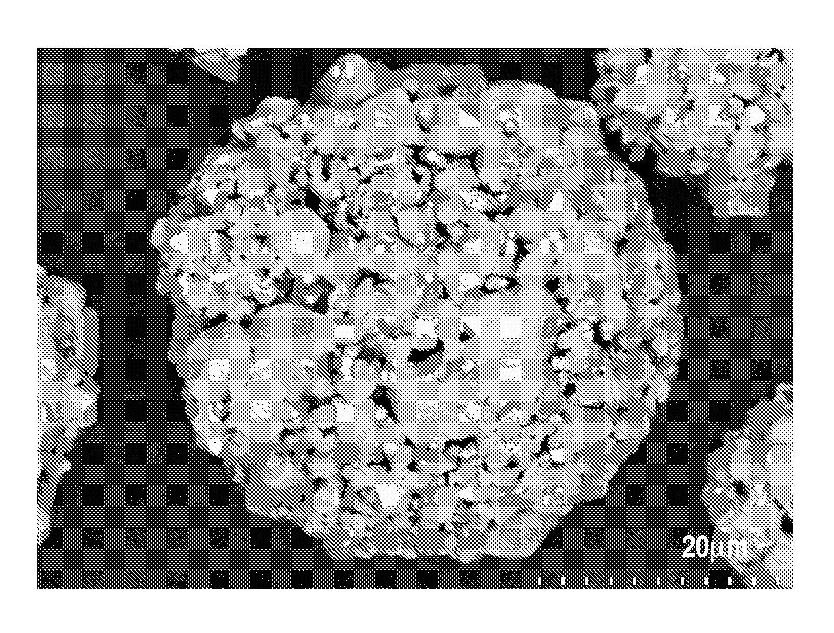
[0315]Magnetic core 5 was prepared in the same way as in Production Example 1 of a porous magnetic core except that production conditions were changed as shown in Table 2A. The crush time in the wet process beads mill in Step 3 was changed to 5 hours and the slurry was not taken out on the way. The physical properties of the obtained magnetic core 5 are shown in Table 2B.

production example 6

of Porous Magnetic Core

[0316]Porous magnetic core 6 was prepared in the same way as in Production Example 1 of a porous magnetic core except that production conditions were changed as shown in Table 2A. The crush time in the wet process beads mill in Step 3 was changed to 4 hours and the slurry was not taken out on the way. The physical properties of the obtained porous magnetic core 6 are shown in Table 2B.

production example 7

of Magnetic Core

[0317]Magnetic core 7 was prepared in the same way as in Production Example 1 of a porous magnetic core except that production conditions were changed as shown in Table 2A. The crush time in the wet process beads mill in Step 3 was changed to 5 hours. Half of the amount of the slurry was not taken out on the way.

[0318]The obtained magnetic core particles were sintered body having a smooth surface. The physical properties of the obtained magnetic core 7 are shown in Table 2B.


PUM


Abstract

A magnetic carrier is provided which uses a toner having high coloring power and enables development to be performed at low electric field intensity and can form high quality images while keeping gradation characteristics. The magnetic carrier includes magnetic carrier particles including at least porous magnetic core particles and a resin. The electric field intensity just before the break-down of the magnetic carrier is 1,300 V/cm or more and 5,000 V/cm or less.

Description

[0001]This application is a continuation of International Application No. PCT / JP2009 / 064093, filed Aug. 4, 2009, which claims the benefit of Japanese Patent Application No. 2008-201075, filed Aug. 4, 2008, and Japanese Patent Application No. 2008-201076, filed Aug. 4, 2008.BACKGROUND OF THE INVENTION[0002]1. Field of the Invention[0003]The present invention relates to a magnetic carrier to be contained in a developer which is used for electrophotography and an electrostatic recording method, a two-component developer having this magnetic carrier and a toner and an image forming method using a two-component developer.[0004]2. Description of the Related Art[0005]The process of developing an electrostatic charge image in electrophotography includes causing charged toner particles to adhere to the electrostatic charge image by utilizing an electrostatic interaction with the electrostatic charge image to thereby conduct image formation. A developer for developing an electrostatic charge ...

Claims


Application Information

Patent Timeline
IPC IPC(8): G03G9/083G03G13/08
CPCG03G9/10G03G9/107G03G9/1136G03G9/1131G03G9/1075G03G9/1085G03G9/08G03G9/108
Inventor BABA, YOSHINOBUISHIGAMI, KOHENDO, TOMOKOFUJIKAWA, HIROYUKINAKAMURA, KUNIHIKOKOMATSU, NOZOMUINOUE, CHIKAITAKURA, TAKAYUKI
Owner CANON KK
Why Eureka
Try Eureka