Periotome

a technology of periotome and spleen, which is applied in the field of periotome, can solve problems such as distinctive bending of instruments, tissue and bone damage, and problems such as arising

Inactive Publication Date: 2010-06-10
LASNER JEFFREY IRWIN +1
View PDF12 Cites 4 Cited by
  • Summary
  • Abstract
  • Description
  • Claims
  • Application Information

AI Technical Summary

Benefits of technology

[0007]In order that the invention may be more clearly understood, it will now be disclosed in detail with reference to the accompanying drawings, in which:
[000

Problems solved by technology

While the traditional type of periotome described above has facilitated the extraction of teeth, problems have arisen since the instrument must have a thin blade but not sharp in order to enter the periodontal ligament space and operate without tearing adjacent

Method used


Image

  • Periotome
  • Periotome
  • Periotome

Examples


Embodiment Construction

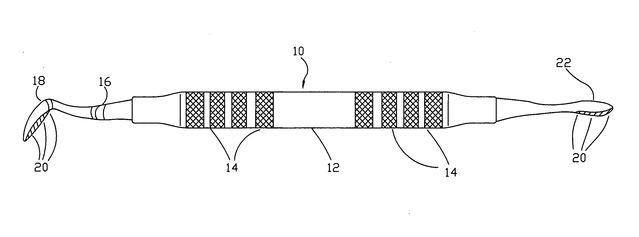
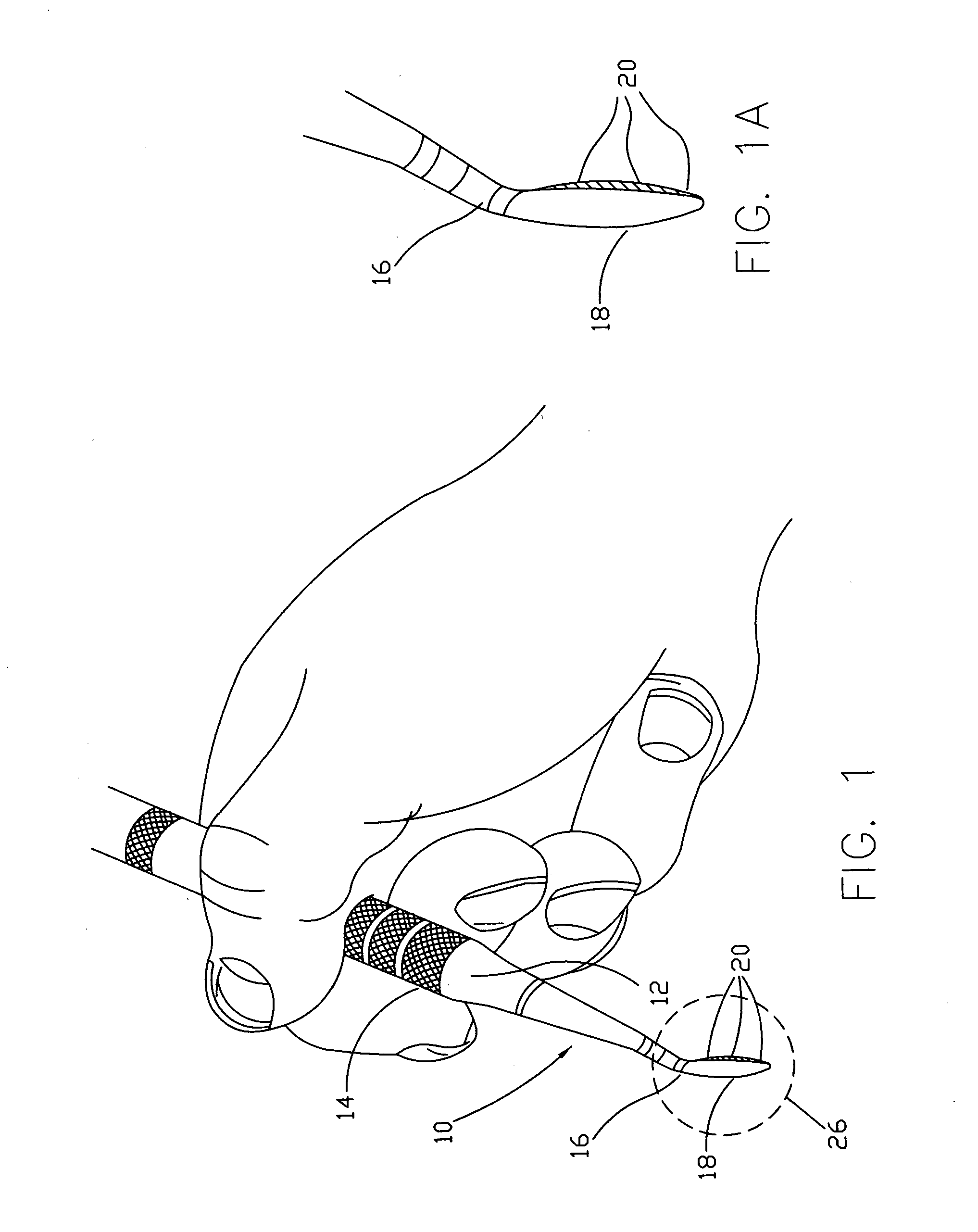
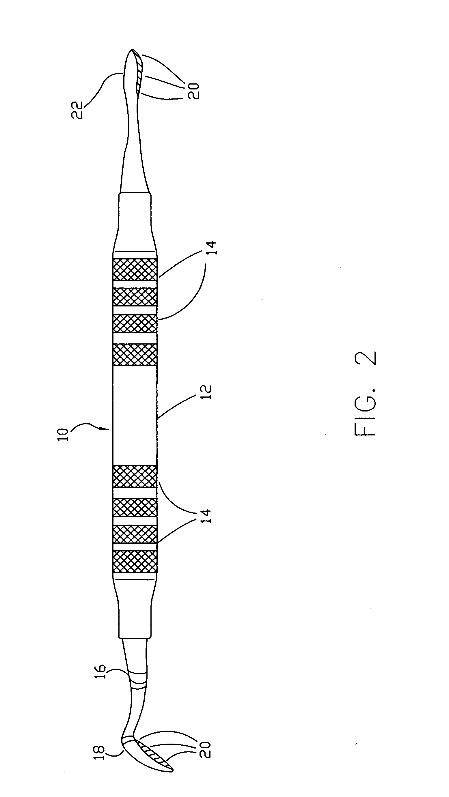
[0014]The periotome instrument, as seen in FIG. 1, in the hands of a dental professional and referred to generally by the numeral 10 has a generally cylindrical body or handle 12 having knurled bands 14 for preventing slipping of the instrument in the user's hands. One end of the instrument 16, as seen in FIGS. 1 and 2 is provided with an angled blade 18 offset from the handle 12. The blade is provided with a multiplicity of micro-serrations 20, serving as cutting edges for the instrument. Although the illustrations show micro-serrations on one side of the thin blade 18, preferably fabricated of stainless steel it should be understood that it is within the concept of the invention to provide micro-serrations on both sides of the blade 18. Thus, the blade 18 functions as a saw in an up and down motion, as seen in FIGS. 4, 5 and 6 of the drawings. In this regard, thin but strong blades engage the ligament fibers individually rather than as a bundle to cut more efficiently, thus prepar...


PUM


Abstract

A periotome for use in dental extractions and in placing of dental implants. The dental instrument is provided with a thin blade having cutting surfaces that cut the ligaments which bind the tooth to the bone in an up and down sawing motion.

Description

[0001]The present invention relates to tooth extractions. Roots of each tooth are encased in the bone in the mouth. The tooth's hole in the bone is a tooth socket. The tooth is held physically in the socket by means of periodontal ligaments fillers which physically binds the tooth to the bone. In order to extract a tooth from its socket a dentist must espand the tooth from its socket with an instrument and also he or she must separate the ligament or fibrous membrane which connects the tooth to the bone. The surgical procedure is also used in the placing of dental implants.BACKGROUND OF THE INVENTION[0002]In the past, the instrument used to perform the above procedure was an elevator which was used to loosen the tooth, widen the space in the bone, and break the ligament which are tiny elastic fibers that attach the tooth to the bone. Once this is accomplished the tooth can be removed from the bone and lifted out of the tooth socket.[0003]Periodontal ligament fibers are progressively...

Claims


Application Information

Patent Timeline
IPC IPC(8): A61C3/02
CPCA61C3/14
Inventor LASNER, JEFFREY IRWINLASNER, MICHAEL ERIC
Owner LASNER JEFFREY IRWIN
Why Eureka
Try Eureka