Slurry phase polymerisation process

a polymerisation process and slurry phase technology, applied in chemical/physical/physical/physical-chemical stationary reactors, chemical/physical/physical-chemical processes, chemical apparatus and processes, etc., can solve the problems of increasing the design size and complexity of the pump, increasing the energy consumption of slurry concentration, and increasing fouling, so as to reduce the energy consumed per unit weight of polymer produced, avoid unacceptable reactor fouling, and reduce the effect of loop reactor energy consumption

Active Publication Date: 2010-06-10
INEOS EURO LTD
View PDF6 Cites 325 Cited by
  • Summary
  • Abstract
  • Description
  • Claims
  • Application Information

AI Technical Summary

Benefits of technology

[0011]One advantage of the present invention is that the specific energy consumption (i.e. the energy consumed per unit weight of polymer produced) of the loop reactor is reduced whilst maintaining a given reactor residence time and avoiding unacceptable reactor fouling. The invention is especially advantageous when it is desired to design and operate a reactor at high solids loadings when it has previously been considered necessary to use what have now been found to be excessively high loop circulation velocities.
[0012]This invention relates to a method and apparatus for continuous polymerization of olefins, preferably alpha mono olefins, in an elongated tubular closed loop reaction zone. The olefin(s) is continuously added to, and contacted with, a catalyst in a hydrocarbon diluent. The monomer(s) polymerise to form a slurry of solid particulate polymer suspended in the polymerisation medium or diluent.
[0013]Typically, in the slurry polymerisation process of polyethylene, the slurry in the reactor will comprise the particulate polymer, the hydrocarbon diluent(s), (co) monomer(s), catalyst, chain terminators such as hydrogen and other reactor additives. In particular the slurry will comprise 20-75, preferably 30-70 weight percent based on the total weight of the slurry of particulate polymer and 80-25, preferably 70-30 weight percent based on the total weight of the slurry of suspending medium, where the suspending medium is the sum of all the fluid components in the reactor and will comprise the diluent, olefin monomer and any additives; the diluent can be an inert diluent or it can be a reactive diluent in particular a liquid olefin monomer; where the principal diluent is an inert diluent the olefin monomer will typically comprise 2-20, preferably 4-10 weight percent of the slurry.

Problems solved by technology

The increased velocity and head requirement of the loop has however led to increasing pump design sizes and complexity, and energy consumptions as slurry concentrations increase.
Inadequate cross-sectional distribution could lead to increased fouling, reduced heat transfer and reduced polymer productivity and homogeneity.
Construction and commissioning of new commercial plants is very expensive and therefore new designs seek to avoid or minimise changes to operating parameters that are seen to increase risk to the successful operation of the new unit.

Method used


Image

  • Slurry phase polymerisation process
  • Slurry phase polymerisation process
  • Slurry phase polymerisation process

Examples


example 1

[0089

[0090]In the following Example, ethylene was polymerised in two reactors in series. The first reactor had a volume of 96 m3 and an internal diameter along over 98% of its length of 730 mm. The solids content was 27-28 vol %. The volumetric solid content is defined as (Volumetric PE production rate / Volume of slurry exiting the reactor), where:[0091]Volumetric PE production rate=(Ethylene mass feed−Ethylene mass flow exiting reactor) / density of PE][0092]Volume of slurry exiting the reactor=Volume of liquid exiting+volumetric PE production rate[0093]Volume of liquid exiting the reactor=[Sum of mass feeds in−PE mass production] / liquid density[0094]The PE density is measured on dry and degassed powder.

[0095]The density of liquid is calculated based on any suitable model (using composition, temperature and pressure).

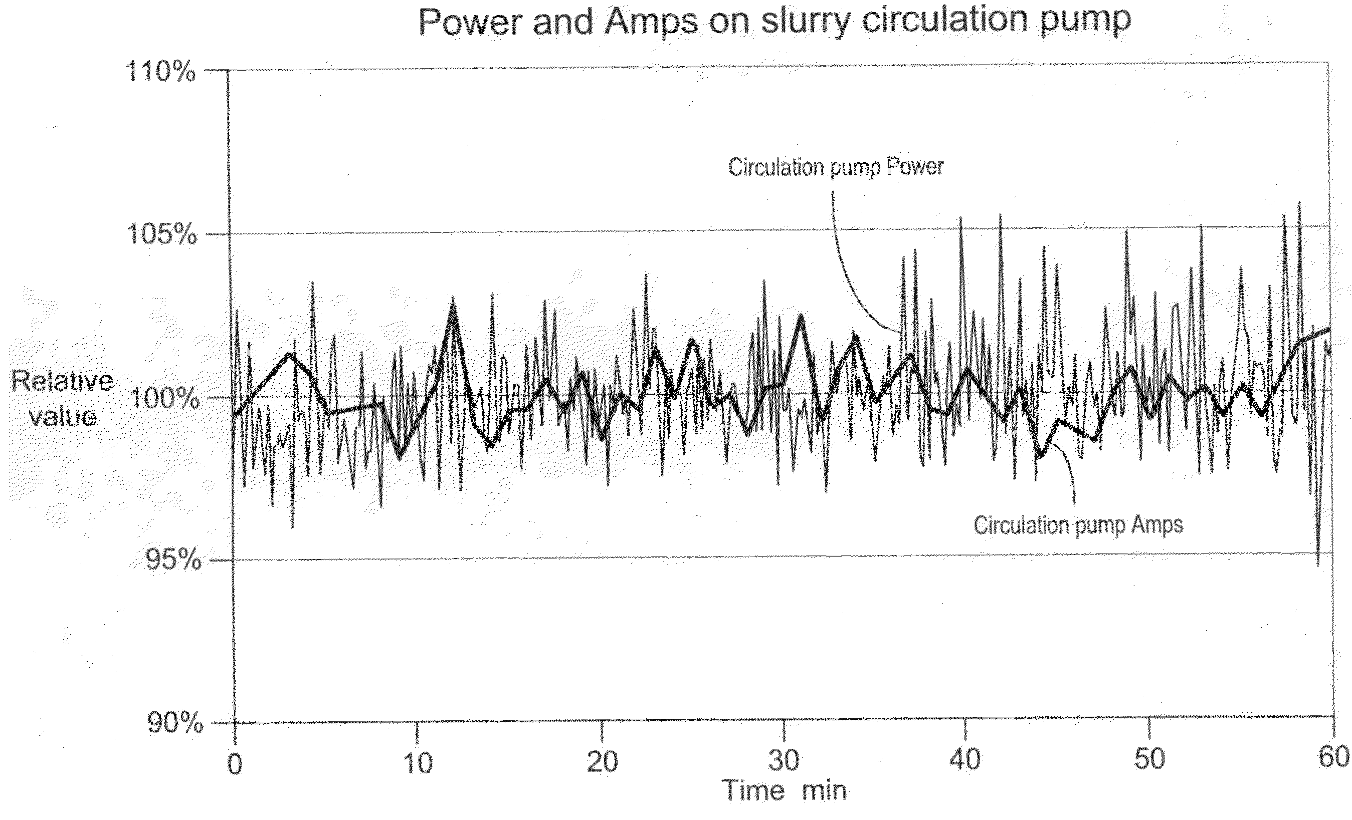
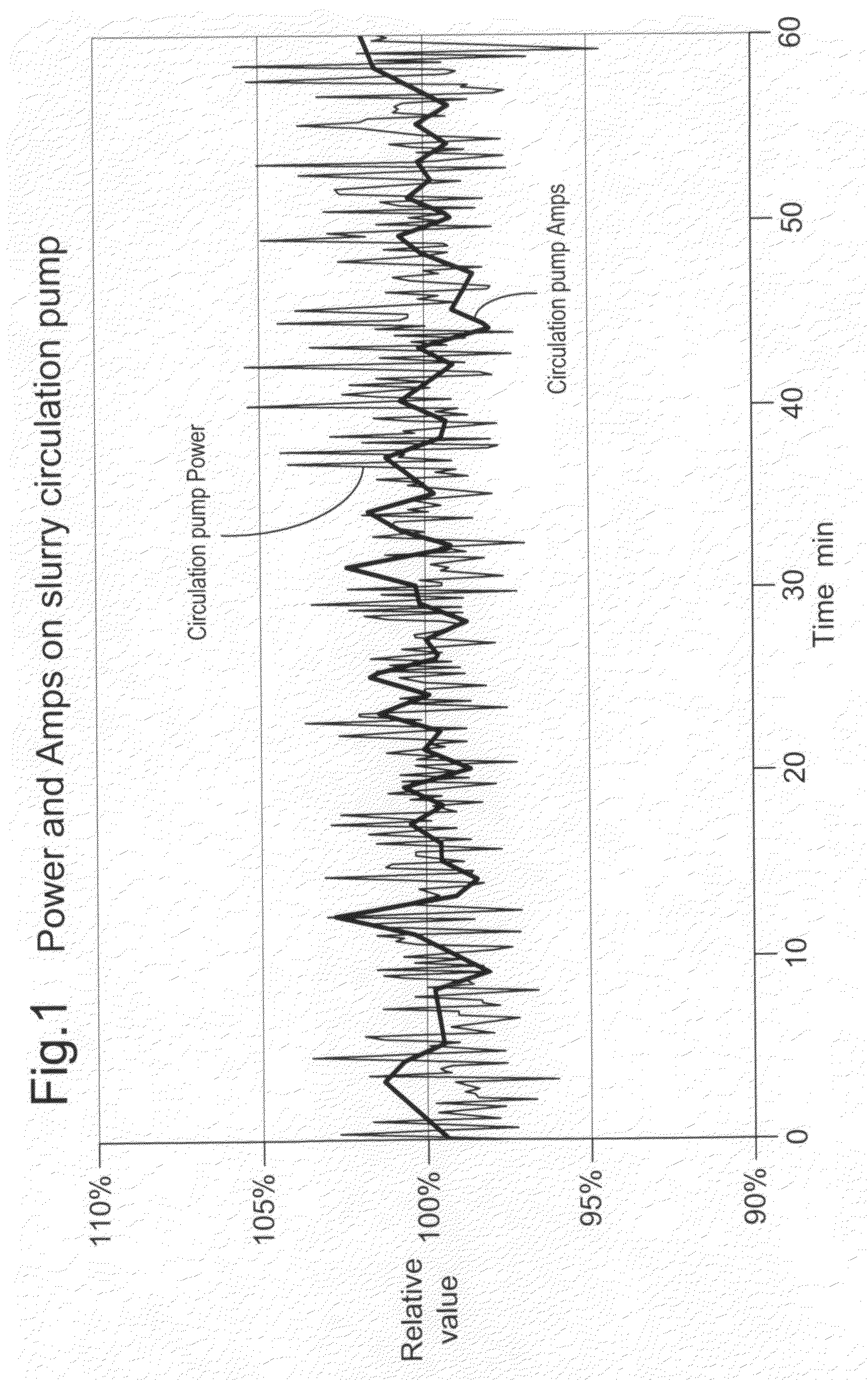
[0096]Circulation Pump Power Requirement

[0097]The power requirement of the circulation pump inside the loop reactor is affected not only by the pressure of the flow, but ...


PUM

PropertyMeasurementUnit
diameteraaaaaaaaaa
diameteraaaaaaaaaa
diameteraaaaaaaaaa

Abstract

A process for controlling a slurry phase (co-) polymerisation process in the presence of a polymerisation catalyst, which comprises maintaining the density SPAN of the polymer powder particles (defined as the absolute value of the density difference in g / cm3 between the average density of the polymer particles exiting the reactor with particle size above D90 and the average density of the material with particle size below D10) below 0.005, preferably below 0.003, more preferably below 0.0026, most preferably below 0.0023.

Description

CROSS REFERENCE TO RELATED APPLICATIONS[0001]This application is a divisional of application Ser. No. 12 / 227,700 filed Nov. 25, 2008, which claims priority to European Application Nos. 06252746.0, filed May 26, 2006, 06252748.6, filed May 26, 2006, and 0625274.8, filed May 26, 2006, which is a 371 of PCT / GB2007 / 001862, filed May 18, 2007, the entire contents of each of which are hereby incorporated by reference.SLURRY PHASE POLYMERISATION PROCESS[0002]The present invention is concerned with olefin polymerisation in slurry phase loop reactors, in particular in multiple reactor systems.BACKGROUND OF THE INVENTION[0003]Slurry phase polymerisation of olefins is well known wherein an olefin monomer and optionally olefin comonomer are polymerised in the presence of a catalyst in a diluent in which the solid polymer product is suspended and transported.[0004]This invention is specifically related to polymerisation in at least one loop reactor of a multiple reactor system where the slurry i...

Claims


Application Information

Patent Timeline
Patent Type & Authority Applications(United States)
IPC IPC(8): C08F2/01C08F110/02
CPCB01J19/1837Y10S526/918B01J2219/0004B01J2219/00164B01J2219/00166B01J2219/00173B01J2219/00184B01J2219/00186B01J2219/00254C08F10/02C08F110/02C08F210/16B01J19/2435Y10S526/909C08F2/001C08F2500/12C08F2500/05C08F2500/08B01J8/025B01J19/18B01J19/24C08F10/00C08F2/14
Inventor LEE, STEPHEN KEVINMARISSAL, DANIELWALWORTH, BRENT R.
Owner INEOS EURO LTD
Why Eureka
Try Eureka