Device And Method For Improving Function Of Heart Valve
a heart valve and device technology, applied in the field of heart valve repair, can solve the problems of valve leakage, valve support may become non-functional, valve function insufficiency, etc., and achieve the effect of reducing the amount of time used for repair, preventing or reducing the backflow of blood, and convenient repair
- Summary
- Abstract
- Description
- Claims
- Application Information
AI Technical Summary
Benefits of technology
Problems solved by technology
Method used
Image
Examples
first embodiment
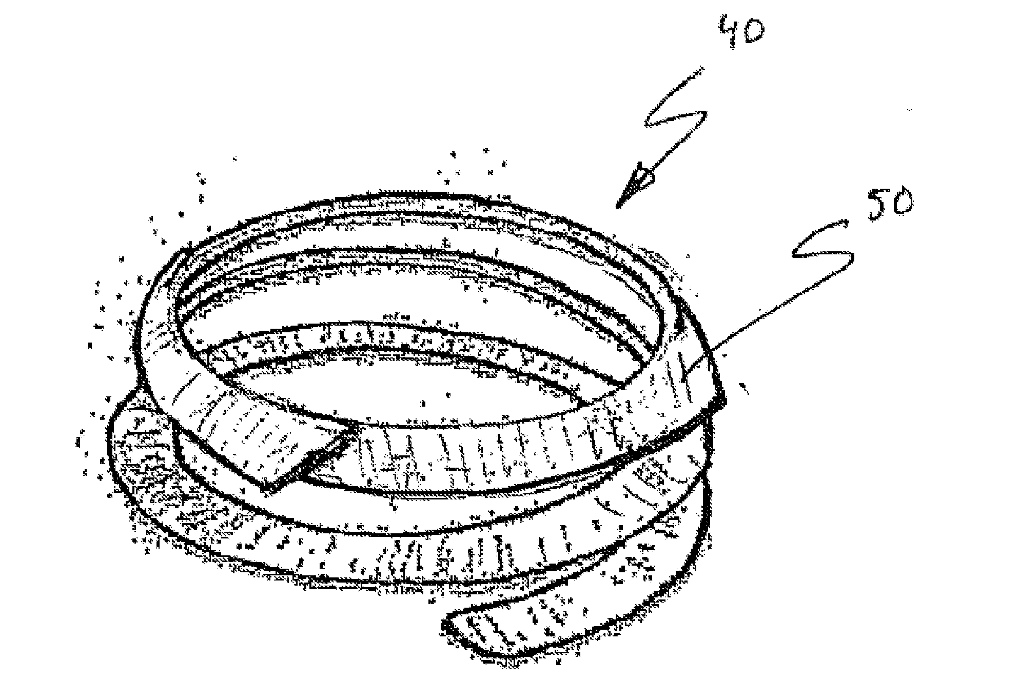
[0090]A body 41 comprised in a device 40 according to the present invention is shown in FIGS. 2 and 3. The body 41 comprises a first and a second loop-shaped support 42, 44.
[0091]As used herein, the term “loop-shaped” should be construed as a curved shape that may be closed, as at least a part of a ring with e.g. a circular, elliptic, or D-shaped form or any other closed form which may fit the shape of the valve annulus. The term “loop-shaped” also includes a curved shape that is open forming an arcuate shape, such as a C-shape or U-shape, which includes an angular turn of at least 180° such that the support may abut valve tissue along a major part of the annular valve shape. The term “loop-shaped” also includes a curved shape overlapping itself to form a portion of a coil.
[0092]The term “loop-shaped” also includes three dimensional curves as mentioned in the previous paragraph.
[0093]The loop shape of at least a part of at least one of the supports 42, 44 may also in some embodiment...
second embodiment
[0114]Now turning to FIG. 6, the device 40 is disclosed. The device differs from that disclosed in FIGS. 4 and 5 in that the flange unit 50 extends from the first loop-shaped support 42 to the second loop-shaped support 44. The flange unit 50 may be formed in one piece or be separated into a first and a second piece, wherein the first piece is connected to the first loop-shaped support and the second piece is connected to the second loop-shaped support. The connection may be a rigid connection or a loose connection. The latter may be achieved by the flange unit being passed onto the loop-shaped support(s).
[0115]The flange unit may be continuous or intermittent along its extension.
[0116]The second embodiment is suitable no matter if the device is to be used for repairing or replacing a valve.
[0117]Now turning to FIG. 7, a third embodiment of the device 40 is disclosed. The device 40 differs from that disclosed in FIGS. 4 and 5 in that the flange unit 50 extends along the second loop-...
fourth embodiment
[0118]Now turning to FIG. 8, the device 40 is disclosed. The device 40 differs from that disclosed in FIGS. 4 and 5 in that the flange unit 50 extends along the second loop-shaped support 44 and forms two flange surfaces 54, both being connected to the second loop-shaped support 44. The flange surfaces 54 are so arranged on the loop-shaped support 44 that they overlap the commissures when the device is arranged in the heart valve abutting the annulus. Thereby the two flange surfaces form a sealing preventing possible leakage of blood from the ventricle side to the atrial side.
[0119]In the above discussed embodiments of the device, the flange unit has been disclosed as being either continuous or intermittent along its extension. The flange unit may further have a non-uniform width varying along its extension. By way of example the width may be larger in a region corresponding to a position overlapping the commissure when the device is arranged in the heart valve abutting the annulus....
PUM
 Abstract
Description
Claims
Application Information
 - R&D
- Intellectual Property
- Life Sciences
- Materials
- Tech Scout
- Unparalleled Data Quality
- Higher Quality Content
- 60% Fewer Hallucinations
Browse by: Latest US Patents, China's latest patents, Technical Efficacy Thesaurus, Application Domain, Technology Topic, Popular Technical Reports.
© 2025 PatSnap. All rights reserved.Legal|Privacy policy|Modern Slavery Act Transparency Statement|Sitemap|About US| Contact US: help@patsnap.com


