Heat exchange element and manufacturing method thereof, heat exchanger, and heat exchange ventilator

Active Publication Date: 2010-06-17
MITSUBISHI ELECTRIC CORP
View PDF13 Cites 11 Cited by
  • Summary
  • Abstract
  • Description
  • Claims
  • Application Information

AI Technical Summary

Benefits of technology

[0020]The heat exchange element according to the present invention includes a spacing member in which one or more first section walls and second section walls are alternately arranged. Therefore, an air current flowing through the heat exchange element flows out from the holes formed in the first section wall, thereby disturbing the air current, and outflow from undesired direction can be suppressed by the second section wall. According to the heat exchanger using the heat exchange element, leakage of a primary air current or a secondary air current can be suppressed as compared with a case that all of the section walls are made as the first section walls. The heat conductivity is enhanced as compared with a case that all the section walls are made as the second section walls. As a result, according to the heat exchange element of the present invention, it is easy to configure a light-weight total-heat type heat exchang

Problems solved by technology

Reduction in the effective moisture permeation area and reduction in the heat conductivity can be a

Method used


Image

  • Heat exchange element and manufacturing method thereof, heat exchanger, and heat exchange ventilator
  • Heat exchange element and manufacturing method thereof, heat exchanger, and heat exchange ventilator
  • Heat exchange element and manufacturing method thereof, heat exchanger, and heat exchange ventilator

Examples


Example

First Embodiment

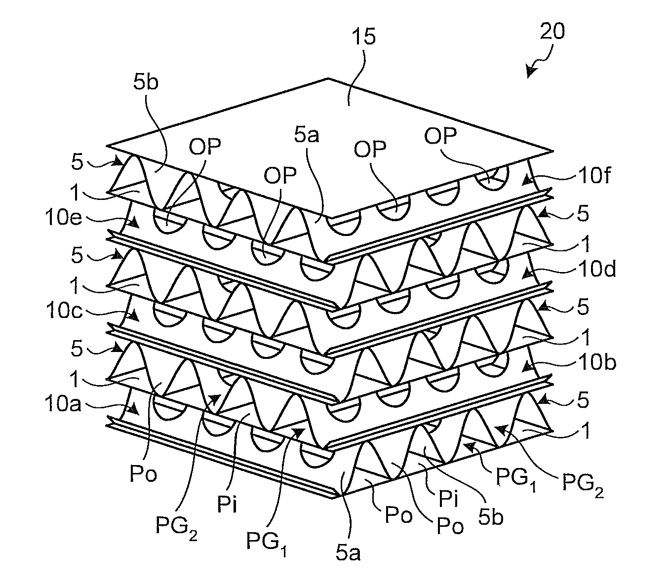
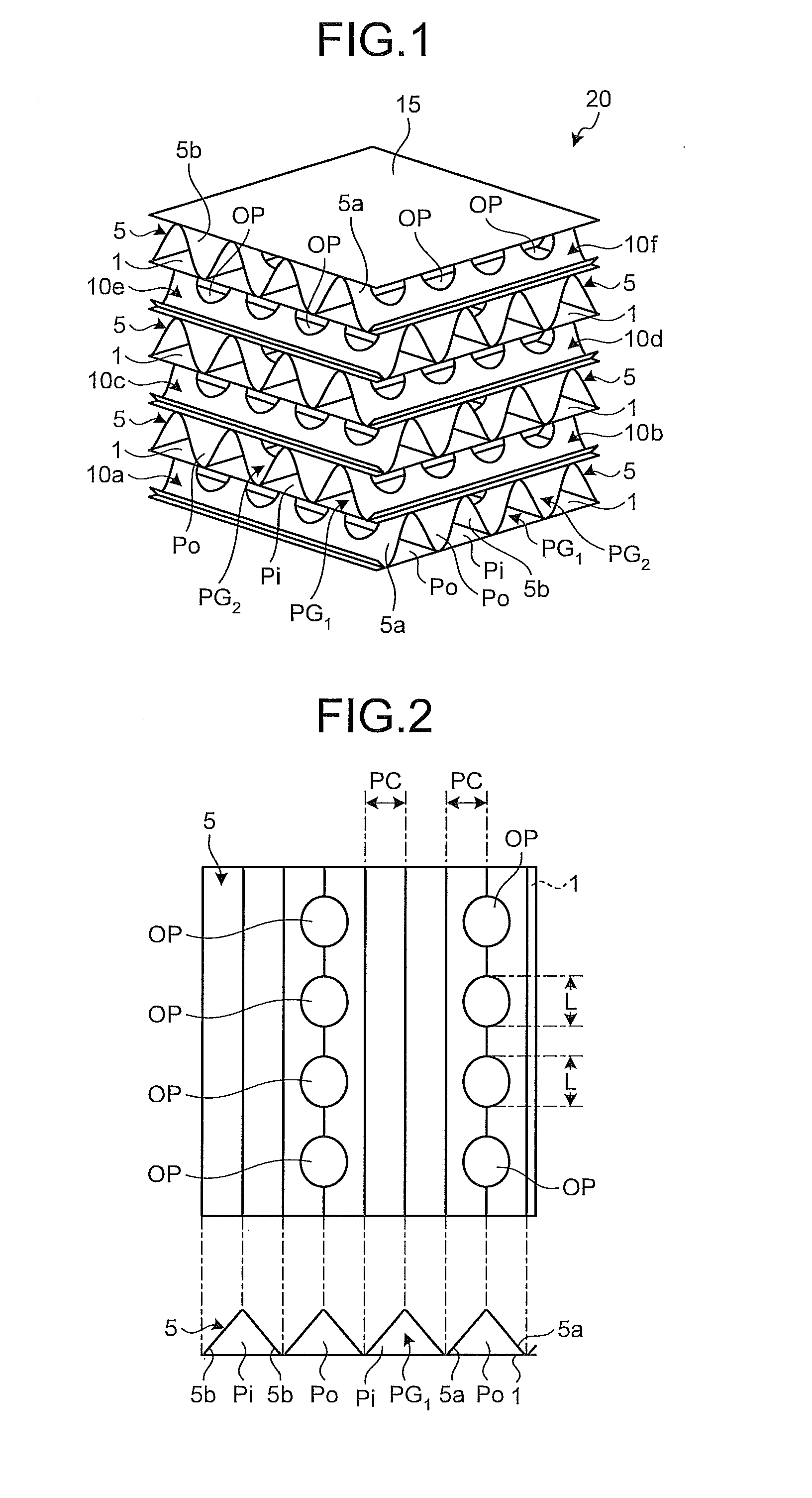
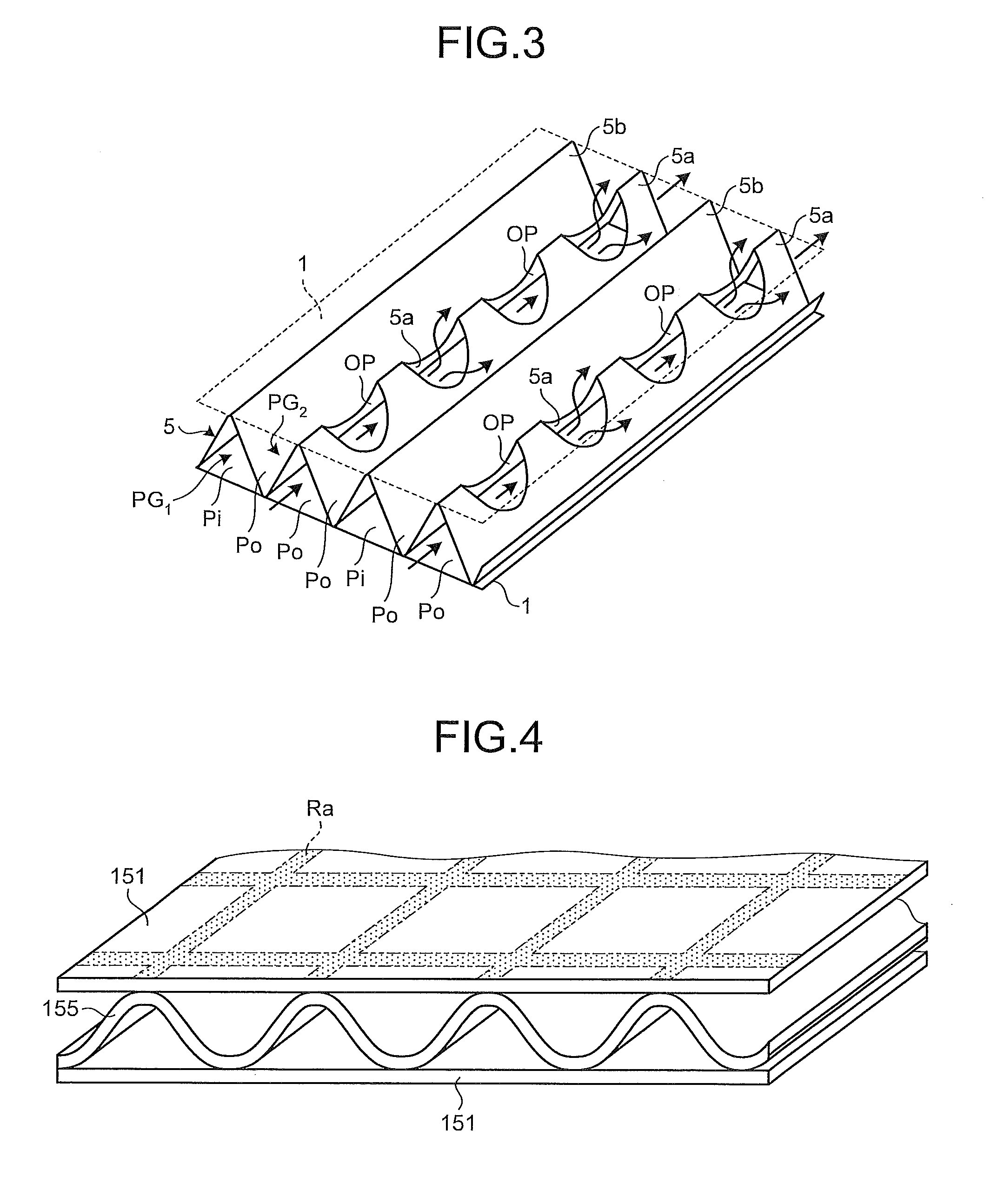
[0060]FIG. 1 is a schematic perspective view of a heat exchange element according to the present invention, FIG. 2 is a schematic diagram of a partition member and a spacing member joined on the partition member constituting a heat exchange element shown in FIG. 1, and FIG. 3 is a schematic perspective view of the spacing member and partition members joined on and under the spacing member constituting the heat exchange element shown in FIG. 1.

[0061]A heat exchange element 20 shown in FIG. 1 is of a cross-flow type having a stacked-layer structure in which sheet-like partition members 1 and corrugated spacing members 5 are alternately joined one another. According to the heat exchange element 20, the stacked-layer structure is formed by laminating six element-constituting units 10a to 10f. A top member 15 is further joined the uppermost element-constituting unit 10f. Each of the element-constituting units 10a to 10f is formed by bonding the spacing member 5 on the par...

Example

Second Embodiment

[0087]FIG. 9 is a schematic perspective view of one example of the heat exchanger. FIG. 10 is a schematic horizontal sectional view of the heat exchanger shown in FIG. 9. A heat exchanger 40 shown in the drawings includes a heat exchange element 20A and a box-like frame body 30 in which the heat exchange element 20A is accommodated.

[0088]The heat exchange element 20A has an identical structure as that of the heat exchange element 20 shown in FIG. 1 except that the number of corrugations in each spacing member and the number of element-constituting units are greater than those of the heat exchange element 20 shown in FIG. 1. Therefore, explanations thereof will be omitted.

[0089]The frame body 30 is a box-like member provided at its four sides with rectangular openings RO. The frame body 30 includes a top plate member 21 covering an upper surface of the heat exchange element 20A, a bottom plate member 23 covering a lower surface of the heat exchange element 20A, and f...

Example

Third Embodiment

[0094]FIG. 11 is a schematic vertical sectional view of one example of the heat exchange ventilator. FIG. 12 is a schematic horizontal sectional view of the heat exchange ventilator shown in FIG. 11. A heat exchange ventilator 70 shown in the drawings includes a casing 50, a heat exchanger 40A arranged in the casing 50, a supply air blower 51, an exhaust air blower 53, two filters 55a and 55b arranged in the casing 50, a lid 59 mounted on the casing 50, and a supply blower tube 61 and an exhaust blower tube 63 connected to the casing 50.

[0095]Two partition walls 41a and 41b are provided in the casing 50 to divide the casing 50 into two in its depth direction. These two partition walls 41a and 41b are separated from each other at a central portion of the casing 50. A supply ventilation passage 43 and an exhaust ventilation passage 45 intersecting with each other at the central portion of the casing 50 are defined in the casing 50 by the two partition walls 41a and 41b...


PUM

PropertyMeasurementUnit
Lengthaaaaaaaaaa
Flow rateaaaaaaaaaa
Widthaaaaaaaaaa

Abstract

According to the present invention, in constituting a heat exchange element having a stacked-layer structure in which sheet-like partition members added a moisture absorbent thereto and spacing members are stacked alternately, the spacing members being joined with the partition members so as to form air flow passages together with the partition members, each of the spacing members includes a plurality of section walls that divide a space between the partition member joined under the spacing member and the partition member joined on the spacing member into a plurality of flow passages, and one or more first section walls formed with holes that bring adjacent flow passages into communication with each other and one or more second section walls formed with no hole that brings adjacent flow passages into communication with each other are alternately arranged in each of the spacing members. The present invention facilitates to constitute a light-weight total-heat type heat exchanger having high heat exchanging efficiency using the heat exchange element.

Description

TECHNICAL FIELD[0001]The present invention relates to a heat exchange element used for an air conditioner such as a heat exchange ventilator, a manufacturing method of the heat exchange element, a heat exchanger, and a heat exchange ventilator using the heat exchange element, and, more particularly to a total-heat type heat exchange element that performs both an exchanging operation of latent heat and an exchanging operation of sensible heat, a manufacturing method of the heat exchange element, a heat exchanger, and a heat exchange ventilator using the total-heat type heat exchange element.BACKGROUND ART[0002]In recent years, hermeticity and high thermal insulation of rooms have been developed for energy saving. Therefore, natural ventilation of rooms cannot be expected so much, and importance of a heat exchange ventilator capable of simultaneously realizing ventilation and air conditioning, particularly a total-heat type heat exchange ventilator having high heat exchanging efficien...

Claims


Application Information

Patent Timeline
IPC IPC(8): F28F1/10B23P15/26
CPCF24F12/006F28D9/0062Y10T29/49373Y02B30/563F28F3/027Y02B30/56F28D9/00F28F3/02
Inventor ARAI, HIDEMOTOTAKADA, MASARUIMAI, TAKANORISUGIYAMA, YOUICHI
Owner MITSUBISHI ELECTRIC CORP
Why Eureka
Try Eureka