Method for Manufacturing a Heat Sink

a heat sink and manufacturing method technology, applied in the direction of lighting and heating apparatus, laminated elements, instruments, etc., can solve the problems of weak fixing strength of insufficient heat conduction from the radiating substrate to the radiating fin, and inability to enhance the fixing strength and heat conductivity between the radiating substrate and the radiating fin, etc., to achieve the effect of enhancing the fixing strength and heat conductivity

Inactive Publication Date: 2007-09-27
HONMA MITSUO
View PDF7 Cites 4 Cited by
  • Summary
  • Abstract
  • Description
  • Claims
  • Application Information

AI Technical Summary

Benefits of technology

[0034] The method for manufacturing a heat sink according to the present invention has the complex uneven surface can be formed by the flattened loops of the metal wire coil of each radiating fin to increase the punctate contact zone between the flat surface of the radiating substrate and the curved parts of the radiating fin, consequently to certainly enhance the fixing strength and heat conductivity between a radiating substrate and radiating fins.

Problems solved by technology

Since the coiled radiating fins have the curved points in touch with the flat surface of the radiating substrate to be secured on the radiating substrate, the heat sink suffers from the disadvantage that fixing strength of the radiating substrate and radiating fins are weak and heat conduction from the radiating substrate to the radiating fins is not sufficient.
However, such a heat sink manufacturing method as described in “Patent Literatures 1-3” has fundamental problems of incapable of enhancing the fixing strength and heat conductivity between the radiating substrate and the radiating fins because the radiating fins are in point contact with the radiating substrate.

Method used


Image

  • Method for Manufacturing a Heat Sink
  • Method for Manufacturing a Heat Sink
  • Method for Manufacturing a Heat Sink

Examples


first embodiment

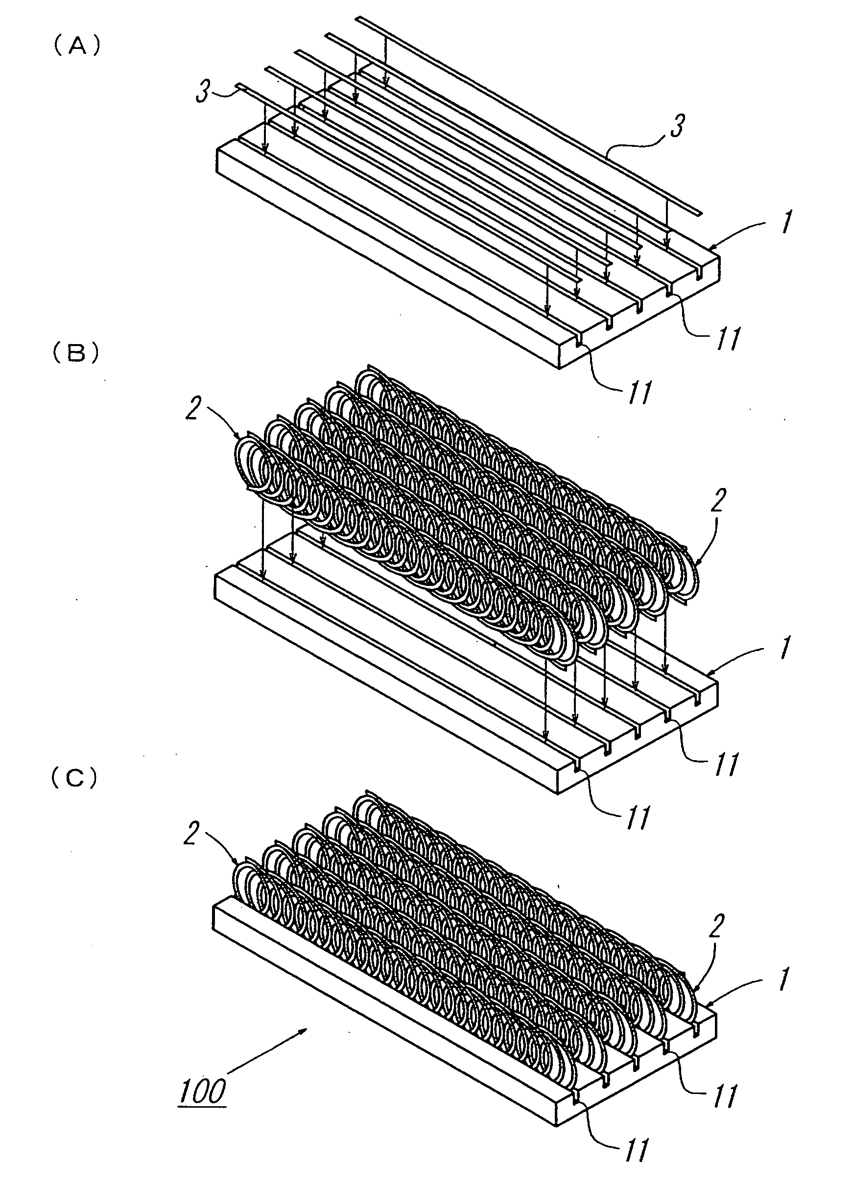
[0048]FIG. 1 through FIG. 6 illustrate the best mode for practicing the method for manufacturing the heat sink according to the invention.

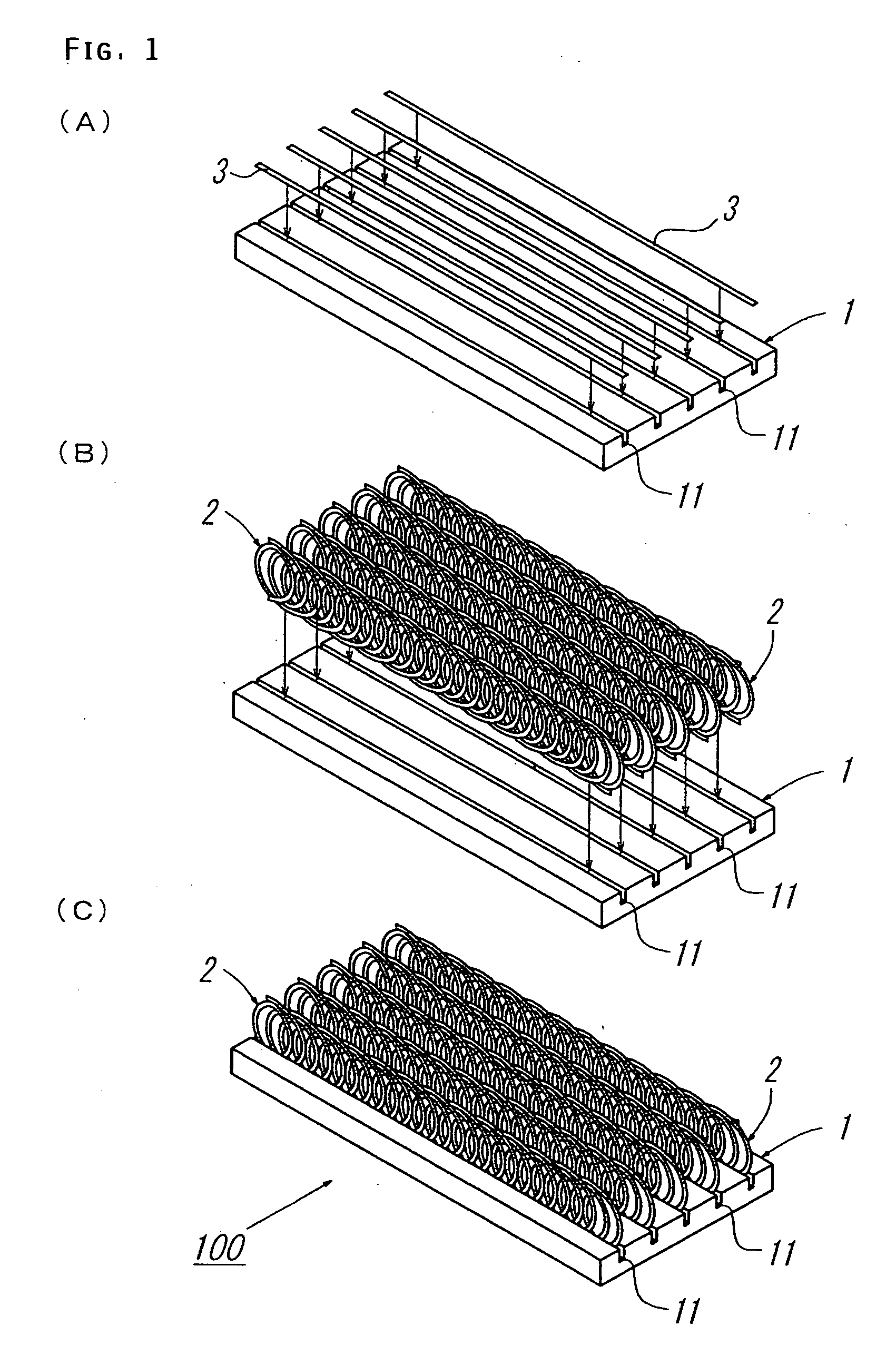
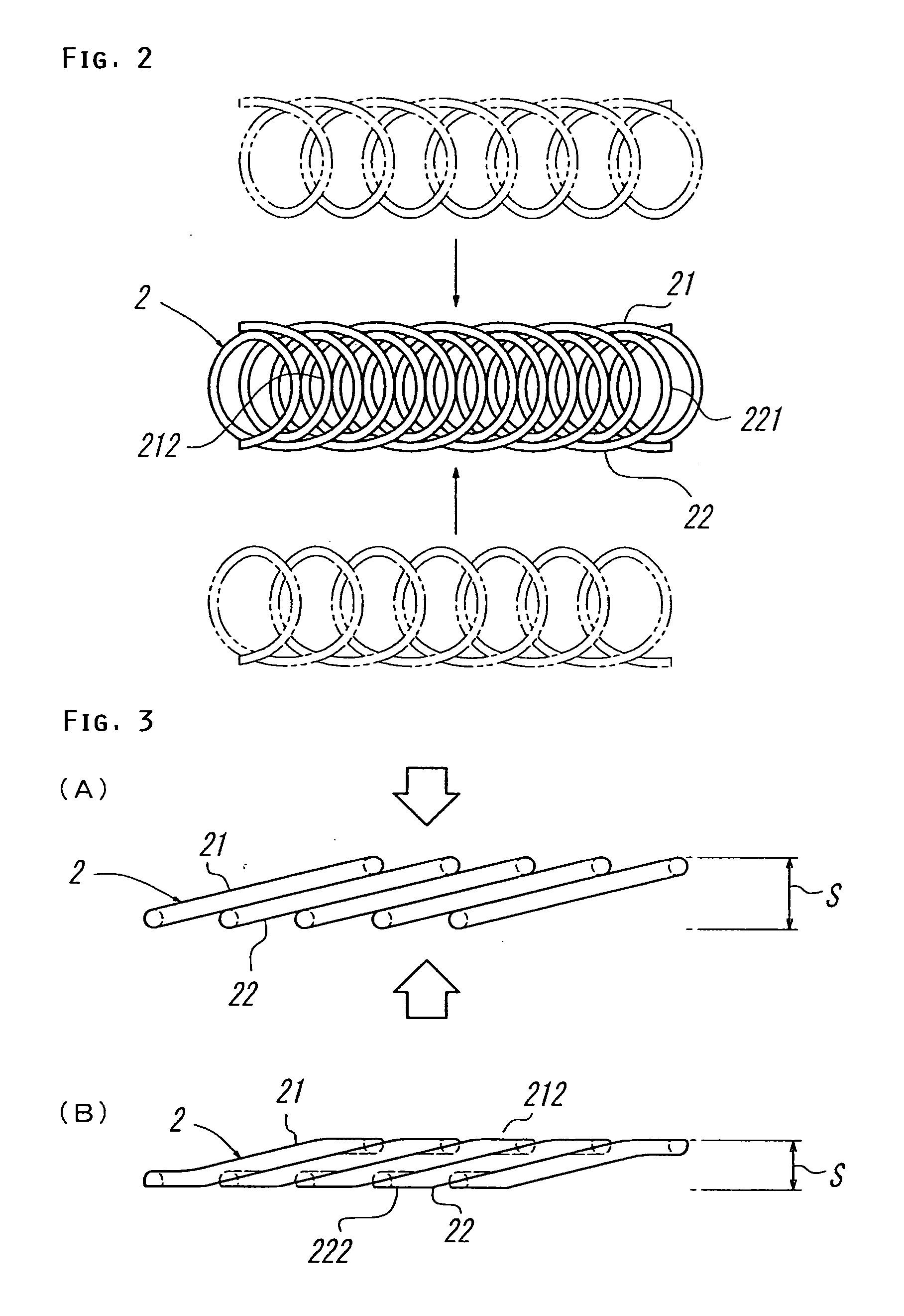
[0049] The heat sink in the first embodiment comprises a radiating substrate 1 and radiating fins 2, which are united by soldering.

[0050] The radiating substrate 1 is formed of a flat plate having high thermal conductivity. To be more specific, it may be made from metallic material such as aluminum, copper, silver and gold or carbon material. As the metallic material, there may be used an alloy of such a metallic material and nickel, magnesium, zinc or silicon. As the occasion demands, it may be subjected to surface treatment with a material having no significant adverse effect on soldering to increase heat conductivity and corrosion resistivity. There are formed slit-like insertion grooves 11 in one surface of the radiating substrate 1 (opposite surface of a mounting surface to be attached to a semiconductor device). The insertion groove 11 may ...

second embodiment

[0064]FIG. 7 shows the best mode for practicing the method for manufacturing the heat sink 100 according to the invention.

[0065] In this second embodiment, the radiating substrate 1 and radiating fins 2 are secured with thermally-conductive adhesive 4.

[0066] The radiating substrate 1 and radiating fins 2 are the same as those in the first embodiment.

[0067] The thermally-conductive adhesive 4 is made by mixing metal powder such as of gold, silver, nickel or the like and / or power of alumina, alumina nitride, silicon nitride, carbon or the like with a binder such as of epoxy resin, silicon resin, acrylate resin, urethane resin or the like.

[0068] The thermally-conductive adhesive 4 may be sprayed intensively onto the insertion grooves 11 in the radiating substrate 1 by using a nozzle 5 as shown in FIG. 7(A).

[0069] The other function and effect of the second embodiment are much the same as the first embodiment processed by soldering, exclusive of the difference between the solder 3 a...

third embodiment

[0073] In the third embodiment as shown in FIG. 8, after inserting the radiating fins 2 into the insertion grooves 11 in the radiating substrate 1, the insertion groove 11 in the radiating substrate 1 is deformed by calking under pressure in the width direction to unite the radiating fins 2 to the radiating substrate 1.

[0074] In the third embodiment, the side edge portions 213 and 223 having the complex uneven surfaces of the coils 21 and 22 of the radiating fins 2 fitted into the insertion grooves 11 are more intricately deformed as the insertion grooves 11 in the radiating substrate 1 are deformed. Thus, the punctate contact portions between the flat surface of the radiating substrate 1 and the curved portions of the radiating fins 2 are significantly enlarged consequently to increase the strength of the union between the radiating substrate 1 and radiating fins 2 and improve the heat conductivity between the radiating substrate 1 and the radiating fins 2.


PUM


Abstract

This invention seeks to provide a method for manufacturing a heat sink capable of enhancing the fixing strength and heat conductivity between a radiating substrate and radiating fins. The heat sink 100 comprises radiating fins 2 formed by winding a metal wire having high thermal conductivity in a coil shape, which is secured on a flat radiating substrate 1 formed of a flat plate having high thermal conductivity. The radiating fins 2 are formed by flattening the radiating fins so as to bring flattened loops of the coiled radiating fins of metal wire into close contact with one another and securing the flattened side edge portions of the radiating fins 2 onto the radiating substrate 1 by soldering.

Description

TECHNICAL FIELD [0001] This invention belongs to the technical field of a method for manufacturing a heat sink mounted on a semiconductor device to radiate heat generated within the semiconductor device to gaseous material, fluid material or the like. BACKGROUND OF THE ART [0002] There has been a heat sink in which radiating fins formed by winding a metal wire having high thermal conductivity in a coil shape is secured on a flat radiating substrate formed of a flat plate having high thermal conductivity. Since the coiled radiating fins have the curved points in touch with the flat surface of the radiating substrate to be secured on the radiating substrate, the heat sink suffers from the disadvantage that fixing strength of the radiating substrate and radiating fins are weak and heat conduction from the radiating substrate to the radiating fins is not sufficient. Thus, there have been the needs to develop a method for manufacturing a heat sink creative with a mechanism for fixing the...

Claims


Application Information

Patent Timeline
Patent Type & Authority Applications(United States)
IPC IPC(8): H01L23/36H01L23/367H05K7/20
CPCH01L23/3677H01L2924/0002H01L2924/00F28F3/022F28F2275/04G06F1/20
Inventor HONMA, MITSUO
Owner HONMA MITSUO
Why Eureka
Try Eureka