Heat dissipation device with heat pipe

a heat pipe and heat dissipation device technology, applied in the direction of semiconductor devices, lighting and heating apparatus, tubular elements, etc., can solve the problem of limiting the applicability of heat pipes to dissipate hea

Inactive Publication Date: 2010-06-17
FU ZHUN PRECISION IND SHENZHEN +1
View PDF9 Cites 6 Cited by
  • Summary
  • Abstract
  • Description
  • Claims
  • Application Information

AI Technical Summary

Problems solved by technology

However, since most parts of the heat pipe of the conventional heat dissipation device are even in diameters, which results in more material is used for forming the evaporating portion of the heat pipe when the evaporating portion can have a smal...

Method used


Image

  • Heat dissipation device with heat pipe
  • Heat dissipation device with heat pipe
  • Heat dissipation device with heat pipe

Examples


Embodiment Construction

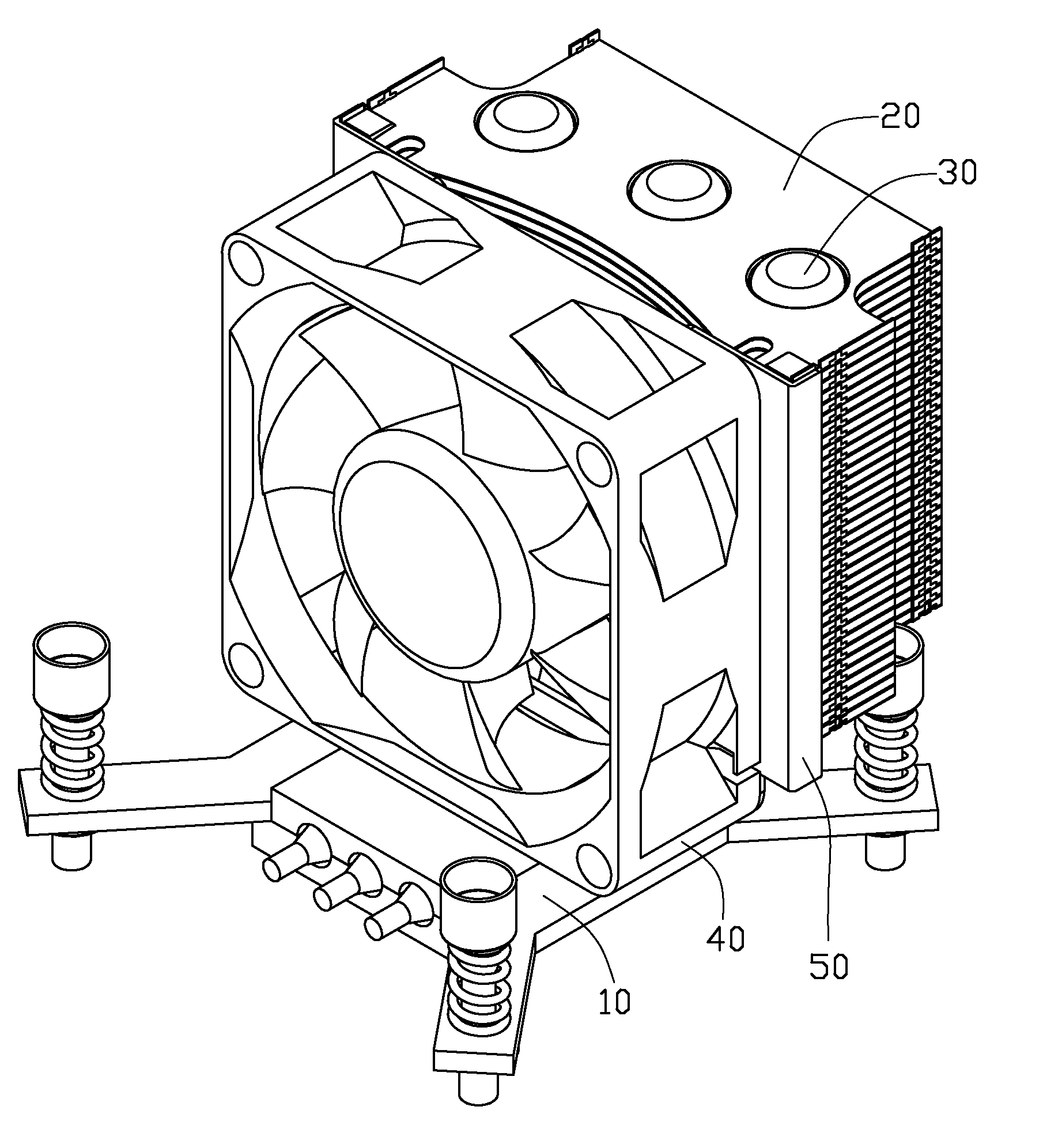
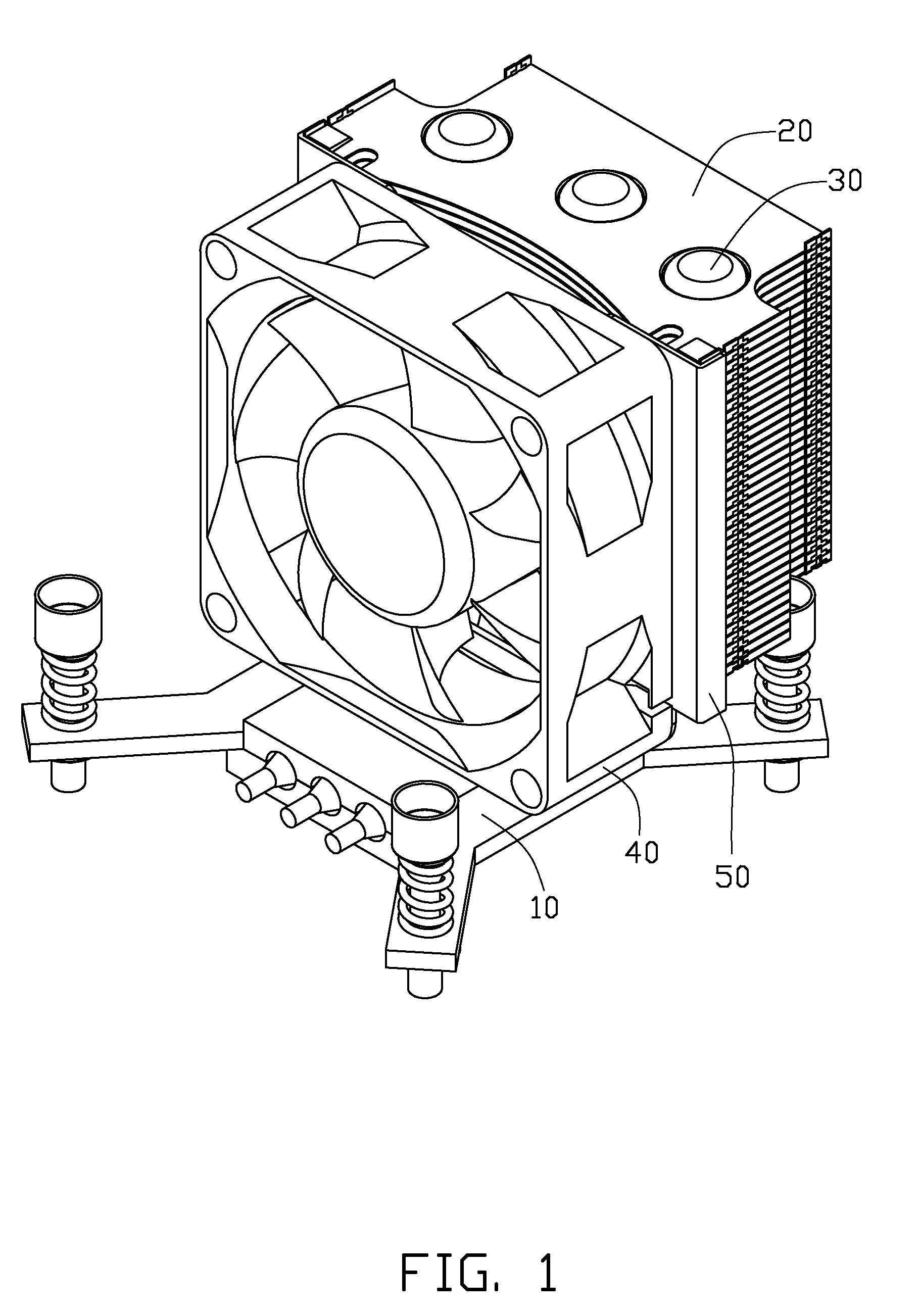
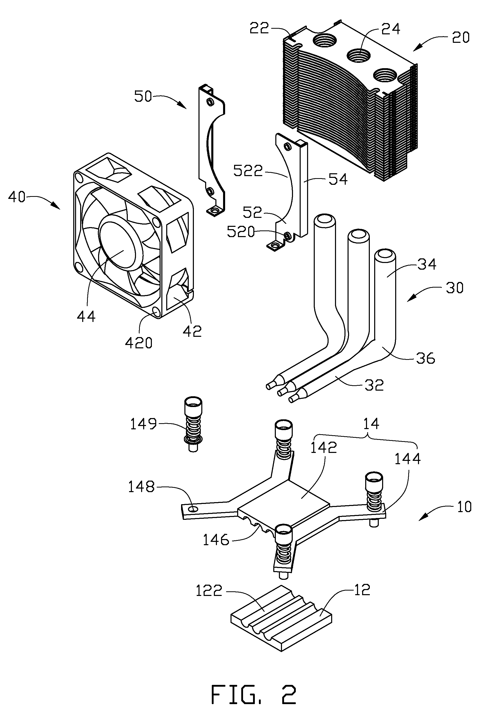
[0011]FIG. 1 shows a heat dissipation device in accordance with an embodiment of the disclosure. The heat dissipation device dissipates heat generated by an electronic device (not shown). The heat dissipation device comprises a heat spreader 10, a fin assembly 20 above the heat spreader 10, three heat pipes 30 thermally connecting the heat spreader 10 with the fin assembly 20, a fan 40 and two fixing brackets 50 fixing the fan 40 to the fin assembly 20.

[0012]Also referring to FIG. 2, the heat spreader 10 is made of metal such as aluminum, copper or an alloy thereof. The heat spreader 10 includes a bottom plate 12 and a top plate 14 above the bottom plate 12. The bottom plate 12 defines three parallel, spaced first grooves 122 in a top thereof. The top plate 14 includes a rectangular body 142 and four ears 144 extending outwardly from four corners of the body 142. The body 142 defines three parallel, spaced second grooves 146 in a bottom thereof, corresponding to the first grooves 12...


PUM


Abstract

A heat dissipation device includes a heat pipe. The heat pipe includes an evaporating section connecting with a heat spreader, a condensing section connecting with a fin assembly, and a connecting section interconnecting the evaporating section and the condensing section. The evaporating section of the heat pipe has a diameter smaller than that of the condensing section.

Description

BACKGROUND[0001]1. Technical Field[0002]The disclosure relates to a heat dissipation device and, more particularly, to a heat dissipation device incorporating heat pipes for removing heat from an electronic device.[0003]2. Description of Related Art[0004]As computer technology continues to advance, electronic components such as central processing units (CPUs) of computers are being made to provide faster operational speeds and greater functional capabilities. When a CPU operates at a high speed in a computer enclosure, its temperature greatly increases. It is desirable to dissipate the heat quickly, for example by using a heat dissipation device attached to the CPU in the enclosure. This allows the CPU and other electronic components in the enclosure to function within their normal operating temperature ranges, thereby assuring the quality of data management, storage and transfer.[0005]A typical heat dissipation device comprises a base contacting an electronic component, a fin assem...

Claims


Application Information

Patent Timeline
IPC IPC(8): F28F1/10
CPCF28D15/0233F28D15/0266F28D15/0275F28F13/08H01L23/3672H01L23/4006H01L2924/0002H01L23/427H01L23/467H01L2924/00
Inventor XU, SHOU-BIAOZHOU, SHI-WENCHEN, CHUN-CHI
Owner FU ZHUN PRECISION IND SHENZHEN
Why Eureka
Try Eureka