Sacrificial anode and treatment of concrete

a technology of concrete and anodes, applied in the field of sacrificial anodes, can solve the problems of difficult power supply problems, restricted oxidation of metals, complex circuits, etc., and achieve the effect of high resistance, high resistance and good use effect of current flow

Active Publication Date: 2010-06-17
GLASS GARETH KEVIN +2
View PDF31 Cites 20 Cited by
  • Summary
  • Abstract
  • Description
  • Claims
  • Application Information

AI Technical Summary

Benefits of technology

[0016]When such an assembly is connected to a metal section to be cathodically protected, for example a steel section in concrete, the potential difference between the metal section and the sacrificial anode is greater than the natural potential difference between the metal section and the sacrificial anode, and therefore a useful level of current flow can be achieved even in circuits with high resistance. Accordingly, the sacrificial anode assembly can be used to provide sacrificial cathodic protection of a metal section in locations whereby sacrificial cathodic protection was not previously able to be applied at a useful level due to the circuit between the metal section and the sacrificial anode being completed by a material, such as an electrolyte, of high resistance. A useful level of protection may also be achieved with compact discrete sacrificial anodes embedded within the concrete wherein the resistance is high because the area and volume of electrolyte contacting the surface of the sacrificial anode is small. Embedding the anode in a cavity ensures that it is strongly attached to the concrete.
[0017]Further, as the potential difference between the metal section and the sacrificial anode is greater than the natural potential difference between the metal section and the sacrificial anode, it is possible to have increased spacing between anodes where a multiplicity of sacrificial anode assemblies are deployed in a structure. This may reduce the total number of assemblies required in a given structure.
[0018]In addition, the assembly of the present invention produces a high initial current. This is in particular useful as it allows the assembly to be used to passivate metals, such as steel, which metals may be in an active corrosion state or may be in new concrete. Furthermore, the assembled anode assembly of the present invention may suitably be located in a concrete or other structure that includes a metal section requiring cathodic protection, or may be encased in a material identical or similar to that of the structure and this encased assembly may then be secured to the exterior of the structure. The look of the structure can therefore be maintained, as no components dissimilar in appearance to the structure itself are present on the exterior of the structure.
[0019]The invention will now be further described in the following examples, with reference to the drawings in which:
[0020]FIG. 1a shows a cross section through a sacrificial anode assembly in accordance with the invention;
[0021]FIG. 1b shows a section A-A through the sacrificial anode assembly as shown in FIG. 1a;

Problems solved by technology

This technique provides corrosion protection for the metal section by the formation of an electrical circuit that results in the metal section acting as a cathode and therefore oxidation of the metal is restricted.
These systems generally require complex circuits to apply the current appropriately and control systems to control the application of the current.
Furthermore, those that are supplied with mains power clearly can encounter difficulties with power supply problems such as power surges and power cuts, whilst those powered by battery have to overcome the issue of locating the battery at an appropriate position, which both allows the battery to function correctly and supports the weight of the battery.
Such impressed current systems may have a battery secured to the exterior of the structure containing the metal sections to be protected, which clearly adversely affects the look of the structure.
The advantage of sacrificial anodes is that they can be used without a power supply, but the disadvantage is that they are consumed.
However, sacrificial metal dissolution occurs at the interface between the sacrificial anode and the electrolyte.
As a result sacrificial anodes applied directly to the concrete surface often exhibit adhesion problems.
Surface applied sacrificial anodes exhibit adhesion problems, while embedded compact discrete anodes lack the power to arrest an aggressive corrosion process because they have to drive more current through a small volume of concrete near the anode.
A problem associated with sacrificial cathodic protection arises from the fact that it is the galvanic voltage between the sacrificial anode and the metal section that drives current through the electrolyte between these components.
Accordingly, the higher the resistance of the electrolyte, the lower the current flow is across the electrolyte between a given metal section and sacrificial anode, and hence the application of sacrificial cathodic protection is restricted.

Method used


Image

  • Sacrificial anode and treatment of concrete
  • Sacrificial anode and treatment of concrete
  • Sacrificial anode and treatment of concrete

Examples


example 1

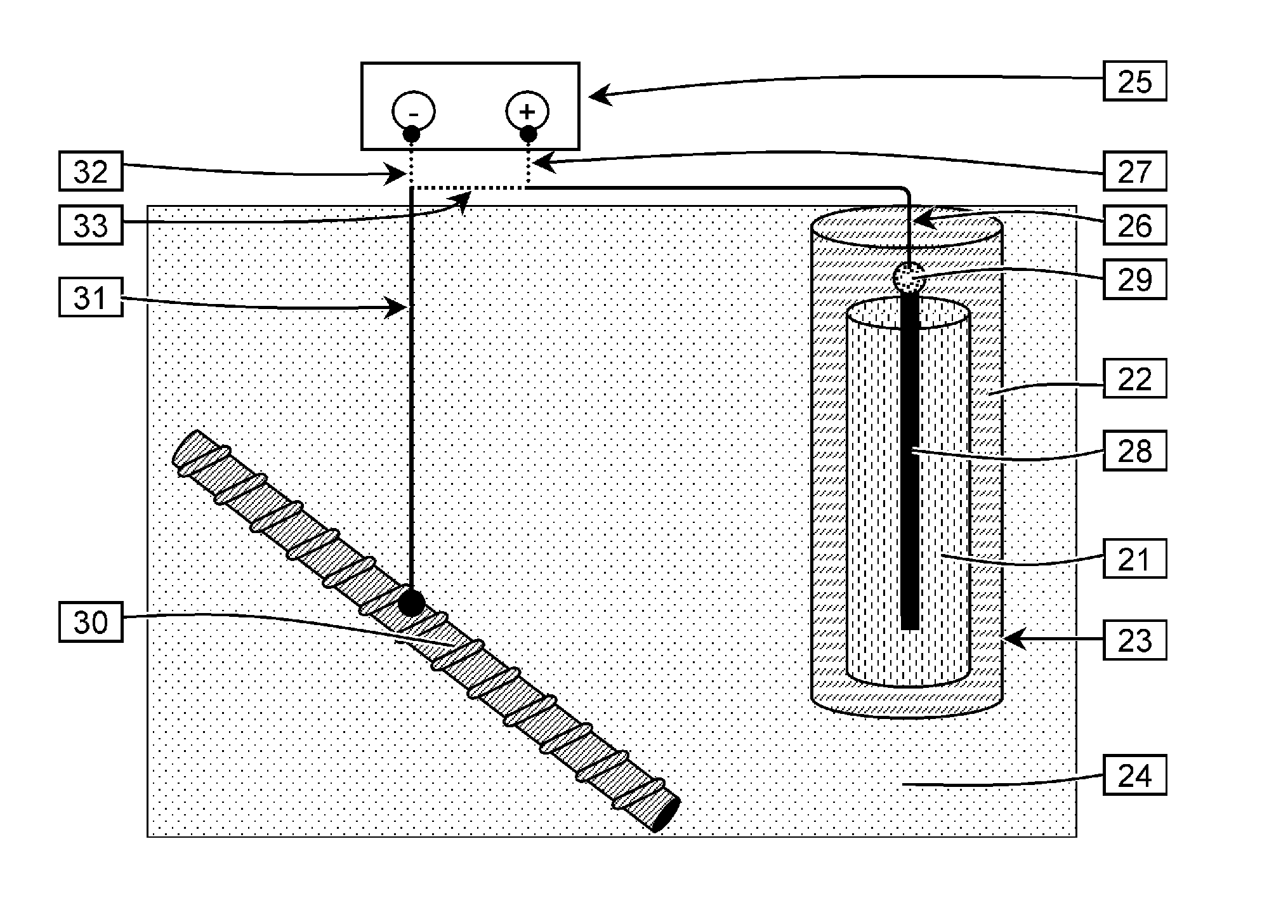
[0026]In one example a sacrificial anode and the cell may be connected together so as to form a single unit; in particular the sacrificial anode assembly may be a single assembled unit. This is, advantageous in that it reduces the complexity of the product and makes it easier to embed the assembly in the structure that includes the metal section to be protected or in a material identical or similar to that of the structure.

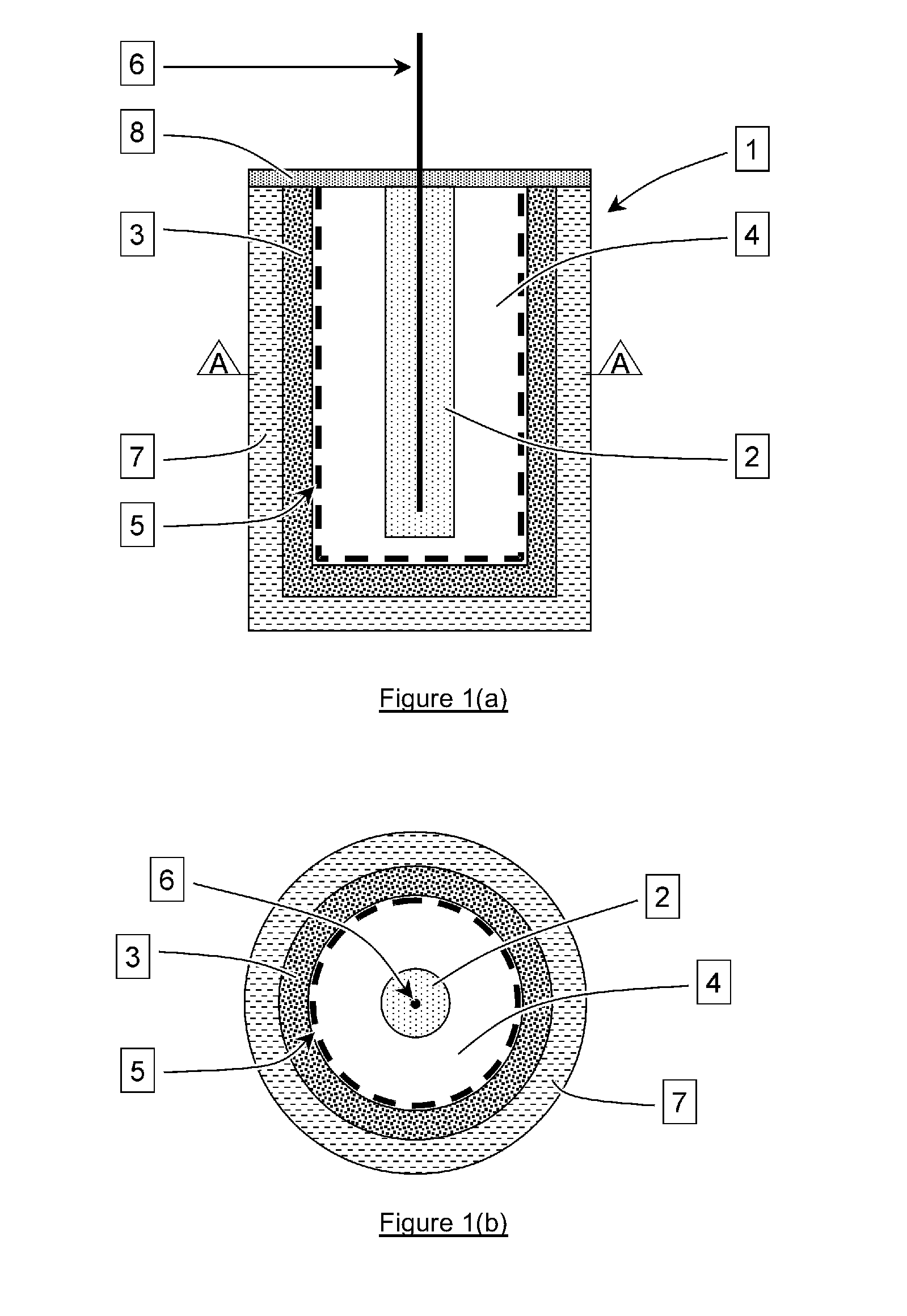
[0027]In particular, the sacrificial anode may be located in the assembly such that it is adjacent to the cell. The sacrificial anode may be of a shape and size corresponding with the shape of at least part of the cell, such that it fits alongside at least part of the cell. In a preferred embodiment the sacrificial anode forms a container within which the cell is located.

[0028]The sacrificial anode may be directly connected to the cathode of the cell, being in direct contact with the cathode of the cell, or may be indirectly connected to the cathode of the cell. I...

example 2

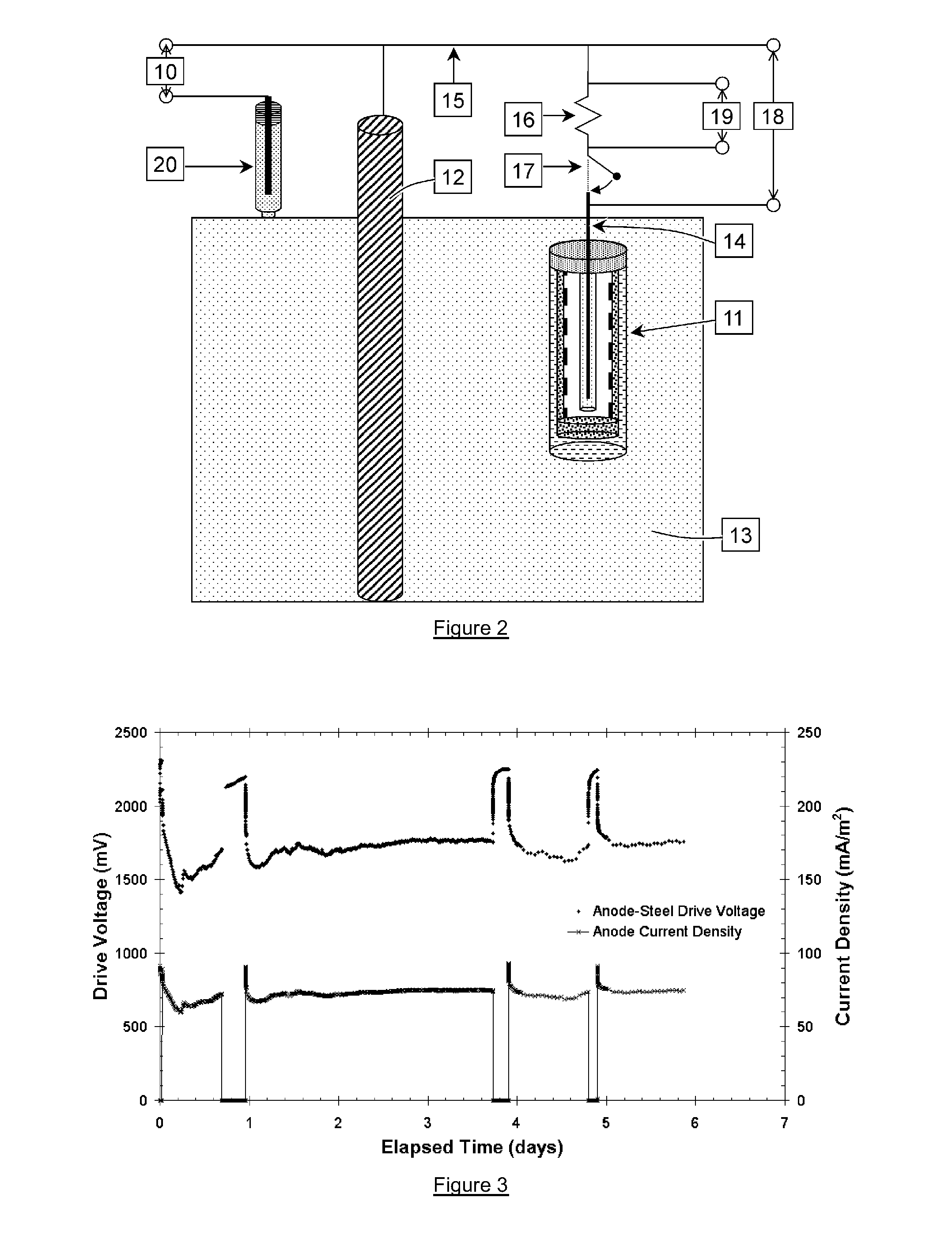
[0044]In another example, the present invention provides a method of cathodically protecting metal in which the sacrificial anode assembly in example 1 above is cathodically attached to the metal via the connector of the assembly. In particular, a method of cathodically protecting steel reinforcement in concrete is provided, in which a sacrificial anode assembly in accordance with the first aspect of the present invention is cathodically attached to the steel.

example 3

[0045]In another example, the present invention provides a reinforced concrete structure wherein some or all of the reinforcement is cathodically protected by the method described in the second example.


PUM

PropertyMeasurementUnit
widthaaaaaaaaaa
diameteraaaaaaaaaa
diameteraaaaaaaaaa

Abstract

A method of protecting steel in concrete is disclosed. A voltage between two connections of a power supply is generated such that current can flow between a negative connection and a positive connection. In a first protection step, one of the connections of the power supply is electrically connected to the steel to be cathodically protected and a sacrificial anode is electrically connected in series with the other connection of the power supply such that the voltage generated by the power supply is added to the voltage generated between the sacrificial anode and the steel to produce a voltage greater than the voltage generated between the sacrificial anode and the steel alone. The power supply may be a cell or battery and may be combined with the sacrificial anode to form a single unit. In a second protection step that may follow the first protection step, the voltage generated by the power supply is no longer present and a current flows between the sacrificial anode and the steel to continue protecting and/or passivating the steel. This may be achieved by connecting the sacrificial anode directly to the steel.

Description

CROSS REFERENCES TO RELATED APPLICATIONS[0001]This application is a continuation in part application from application Ser. No. 11 / 587,647 with a 35 U.S.C. 371(c) date of Apr. 25, 2007 which in turn claims priority from UK patent application numbered GB 0409521.2 filed Apr. 29, 2004. This application is also a continuation in part application from application Ser. No. 11 / 908,858 with a 35 U.S.C. 371(c) date of Sep. 17, 2007 which in turn claims priority from UK patent applications numbered GB 0505353.3 filed Mar. 16, 2005 and from GB 0520112.4 filed Oct. 4, 2005 and from GB 0600661.3 filed Jan. 13, 2006.TECHNICAL FIELD[0002]The present invention relates to sacrificial anode assemblies suitable for use in the sacrificial cathodic protection of steel reinforcements in concrete, to methods of protection of steel reinforcement in concrete and to reinforced concrete structures wherein the reinforcement is protected by sacrificial cathodic protection.BACKGROUND[0003]The cathodic protection...

Claims


Application Information

Patent Timeline
Patent Type & Authority Applications(United States)
IPC IPC(8): C23F13/14C23F13/08C23F13/02
CPCC23F13/06C23F2213/21C23F2201/02
Inventor GLASS, GARETH KEVINDAVISON, NIGELROBERTS, ADRIAN CHARLES
Owner GLASS GARETH KEVIN
Why Eureka
Try Eureka