Sacrificial anode assembly

a technology of anode and assembly, which is applied in the direction of structural elements, building components, building reinforcements, etc., can solve the problems of complex circuits, adversely affecting the appearance of the structure, and the power supply supplied with mains power can encounter power supply problems clearly, so as to maximise the efficiency of the system and reduce the amount of isolating means

Active Publication Date: 2018-05-22
VECTOR CORROSION TECH
View PDF30 Cites 0 Cited by
  • Summary
  • Abstract
  • Description
  • Claims
  • Application Information

AI Technical Summary

Benefits of technology

[0026]As one of the permitted electrical connections of the cell is an electrical connection to the sacrificial anode, the amount of isolating means required can be reduced by increasing the area of the exterior of the cell located adjacent the sacrificial anode. Accordingly, in a preferred embodiment the sacrificial anode is in the shape of a container and the cell is located in the container, for example the sacrificial anode may be in the shape of a can, i.e. having a circular base and a wall extending upwards from the circumference of the base so as to define a cavity, and the cell is located in this can. The remaining areas of the cell that are not covered by the sacrificial anode and that are not covered by their contact with the connector are of course isolated from the environment by isolating means.
[0027]It is preferred that the quantities of the anode and cathode materials utilised in the assembly are such that they will each deliver the same quantity of charge during the life of the assembly, as this clearly maximises the efficiency of this system.

Problems solved by technology

These systems generally require complex circuits to apply the current appropriately and control systems to control the application of the current.
Furthermore, those that are supplied with mains power clearly can encounter difficulties with power supply problems such as power surges and power cuts, whilst those powered by battery have to overcome the issue of locating the battery at an appropriate position, which both allows the battery to function correctly and supports the weight of the battery.
Often, therefore, such impressed current systems have a battery secured to the exterior of the structure containing the metal sections to be protected, which clearly adversely affects the look of the structure.
A problem associated with such cathodic protection arises from the fact that it is the voltage between the sacrificial anode and the metal section that drives current through the electrolyte between these components.
Accordingly, the higher the resistance of the electrolyte, the lower the current flow is across the electrolyte between a given metal section and sacrificial anode, and hence the application of sacrificial cathodic protection is restricted.

Method used


Image

  • Sacrificial anode assembly
  • Sacrificial anode assembly
  • Sacrificial anode assembly

Examples


example 1

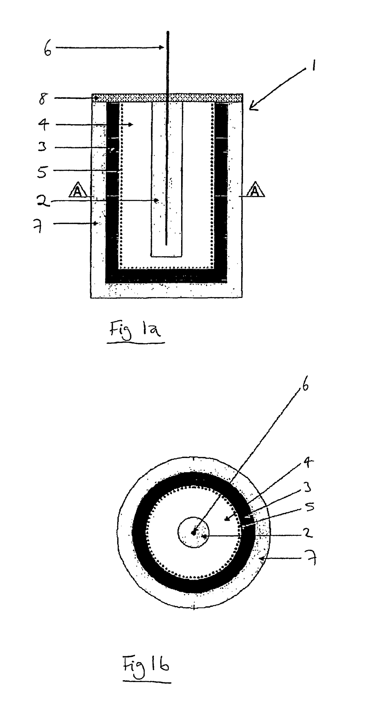
[0040]FIG. 1 shows a sacrificial anode assembly 1 for cathodically protecting a metal section. The assembly comprises a cell, which has an anode 2 and a cathode 3. The cathode 3 is a manganese dioxide / carbon mixture and is in the shape of a can, having a circular base and a wall extending upwards from the circumference of the base, so as to define a cavity. The anode 2 is a solid zinc anode of cylindrical shape, with the solid zinc being cast metal, compressed powder, fibres or foil. The anode 2 is located centrally within the cavity defined by the can shaped cathode 3 and is in contact with electrolyte 4 present in the cavity defined by the can shaped cathode 3, which maintains the activity of the anode. The electrolyte 4 is suitably potassium hydroxide, and may contain other agents such as zinc oxide to inhibit hydrogen discharge from the zinc. A porous separator 5, which is can shaped, is located inside the cavity 3a defined by the cathode 3, adjacent to the cathode 3. Accordingl...

example 2

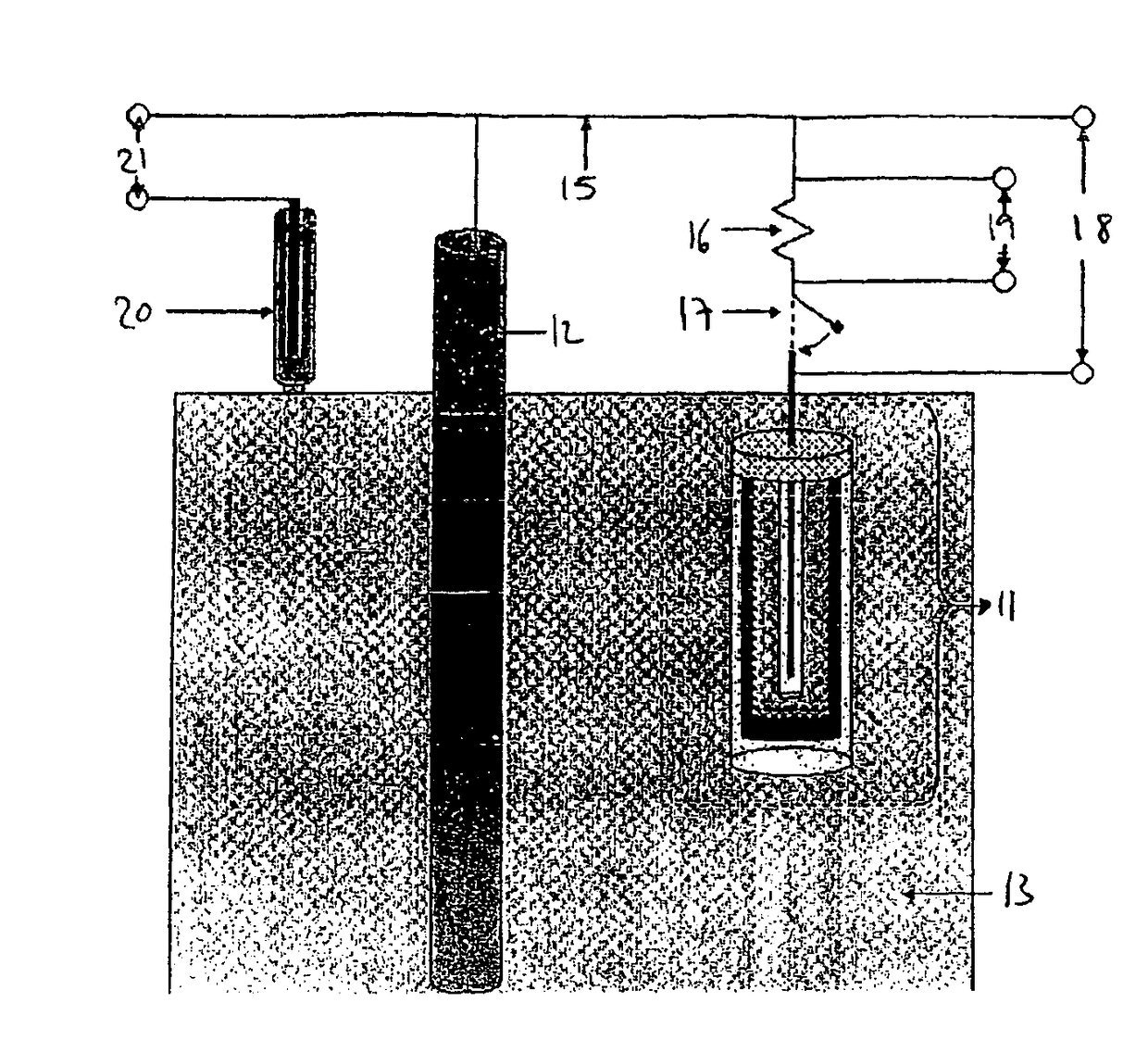
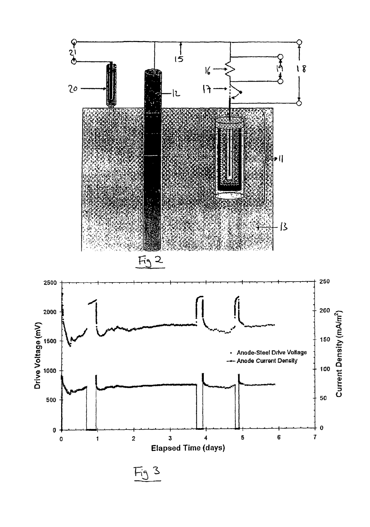
[0044]FIG. 2 shows a sacrificial anode assembly 11 connected to a 20 mm diameter mild steel bar 12 in a 100 mm concrete cube 13 consisting of 350 kg / m3 ordinary Portland cement concrete contaminated with 3% chloride ion by weight of cement.

[0045]The sacrificial anode assembly 11 comprises a cell, which is an AA size Duracell battery, and a sacrificial anode, which is a sheet of pure zinc folded to produce a zinc can around the cell. This zinc is folded so as to contact the positive terminal of the cell, and a conductor 14 is soldered to the negative terminal of the cell. A silicone-based sealant is located over the negative and positive cell terminals so as to insulate them from the environment.

[0046]Prior to placing the sacrificial anode assembly 11 in the concrete cube, potentials were measured using a digital multimeter with an input impedance of 10 Mohm, which showed that the potential between the external zinc casing and a steel bar in moist chloride contaminated sand was 520 m...


PUM

PropertyMeasurementUnit
diameteraaaaaaaaaa
diameteraaaaaaaaaa
driving voltageaaaaaaaaaa

Abstract

A sacrificial anode assembly for cathodically protecting and/or passivating a metal section, comprising: (a) a cell, which has an anode and a cathode arranged so as to not be in electronic contact with each other but so as to be in ionic contact with each other such that current can flow between the anode and the cathode; (b) a connector attached to the anode of the cell for electrically connecting the anode to the metal section to be cathodically protected; and (c) a sacrificial anode electrically connected in series with the cathode of the cell; wherein the cell is otherwise isolated from the environment such that current can only flow into and out of the cell via the sacrificial anode and the connector. The invention also provides a method of cathodically protecting metal in which such a sacrificial anode assembly is cathodically attached to the metal via the connector of the assembly, and a reinforced concrete structure wherein some or all of the reinforcement is cathodically protected by such a method.A sacrificial anode assembly for cathodically protecting and/or passivating a metal section, includes a cell with an anode and a cathode, a connector attached to the anode of the cell for electrically connecting the anode to the metal section to be cathodically protected; and a sacrificial anode electrically connected in series with the cathode of the cell. The cell is otherwise isolated from the environment such that current can only flow into and out of the cell via the sacrificial anode and the connector. A method of cathodically protecting steel in concrete in which such the sacrificial anode assembly is connected to the steel in an initial step of passivation using a higher current and when the first step is terminated the sacrificial anode alone continues to provide protection.

Description

[0001]This application is the US national phase of international application PCT / GB2005 / 001651 filed 29 Apr. 2005 which designated the U.S. and claims benefit of GB 0409521.2, dated 29 Apr. 2004, the entire content of which is hereby incorporated by reference.[0002]The present invention relates to sacrificial anode assemblies suitable for use in the sacrificial cathodic protection of steel reinforcements in concrete, to methods of sacrificial cathodic protection and to reinforced concrete structures wherein the reinforcement is protected by sacrificial cathodic protection.BACKGROUND OF THE INVENTION[0003]The cathodic protection of metal sections of structures is well known. This technique provides corrosion protection for the metal section by the formation of an electrical circuit that results in the metal section acting as a cathode and therefore oxidation of the metal does not occur.[0004]One such known type of system for cathodic protection is the impressed current system, which ...

Claims


Application Information

Patent Timeline
Patent Type & Authority Patents(United States)
IPC IPC(8): C23F13/02C23F13/04C23F13/06C23F13/08C23F13/14C23F13/20E04C5/01C23F13/10
CPCC23F13/06C23F13/10C23F2201/02C23F2213/21E04C5/015
Inventor GLASS, GARETH K.ROBERTS, ADRIAN C.DAVIDSON, NIGEL
Owner VECTOR CORROSION TECH
Why Eureka
Try Eureka