
Method oftransmitting and processing data and transmitter in a wireless communication system

a wireless communication system and wireless communication technology, applied in the field of wireless communication systems, can solve the problems of large amount of time delay, and inability to transmit data, so as to save radio resources and increase communication efficiency

Inactive Publication Date: 2010-06-17
LG ELECTRONICS INC
View PDF10 Cites 96 Cited by
  • Summary
  • Abstract
  • Description
  • Claims
  • Application Information

AI Technical Summary

Benefits of technology

[0007]An object of the present invention is to provide a method for variably configuring a sub-carrier spacing in a wireless communication system based on multiple carriers (i.e., multi-carrier) according to a variety of requirements, so that it increases communication efficiency, and saves radio resources.

Problems solved by technology

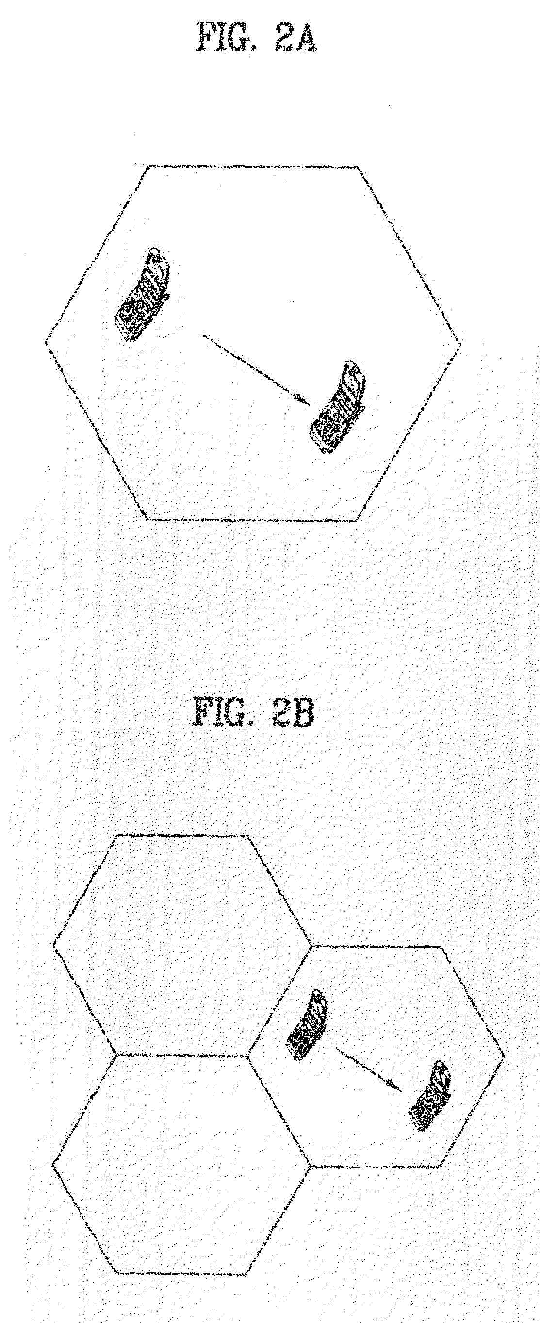
For example, a large amount of time delay occurs in an urban district whereas a small amount of time delay occurs in a vast expanse of land.
A conventional OFDM system has no additional solution for reflecting various frequency dispersive characteristics affected by communication situations, because a cell includes a plurality of mobile terminals (or user equipments) of different speeds, so that the conventional OFDM system is unable to set a focal point on only a specific mobile terminal from among them.
However, if the sub-carrier spacing is fixed at a specific value and a mobile-terminal speed is higher than a reference speed, inter-carrier interference increases by the above-mentioned frequency dispersive characteristics, and orthogonal characteristics of a signal is broken, so that the reliability of data transmission may be deteriorated.
Otherwise, if the mobile-terminal speed is lower than a reference speed, unnecessary resources are allocated so that the utility of frequency resources may be deteriorated.

Method used


Image

  • Method oftransmitting and processing data and transmitter in a wireless communication system
  • Method oftransmitting and processing data and transmitter in a wireless communication system
  • Method oftransmitting and processing data and transmitter in a wireless communication system

Examples


Embodiment Construction

[0025]Reference will now be made in detail to the embodiments of the present invention, examples of which are illustrated in the accompanying drawings. Wherever possible, the same reference numbers will be used throughout the drawings to refer to the same or like parts.

[0026]Prior to describing the present invention, it should be noted that most terms disclosed in the present invention correspond to general terms well known in the art, but some terms have been selected by the applicant as necessary and will hereinafter be disclosed in the following description of the present invention. Therefore, it is preferable that the terms defined by the applicant be understood on the basis of their meanings in the present invention.

[0027]For the convenience of description and better understanding of the present invention, general structures and devices well known in the art will be omitted or be denoted by a block diagram or a flow chart. Wherever possible, the same reference numbers will be u...


PUM


Abstract

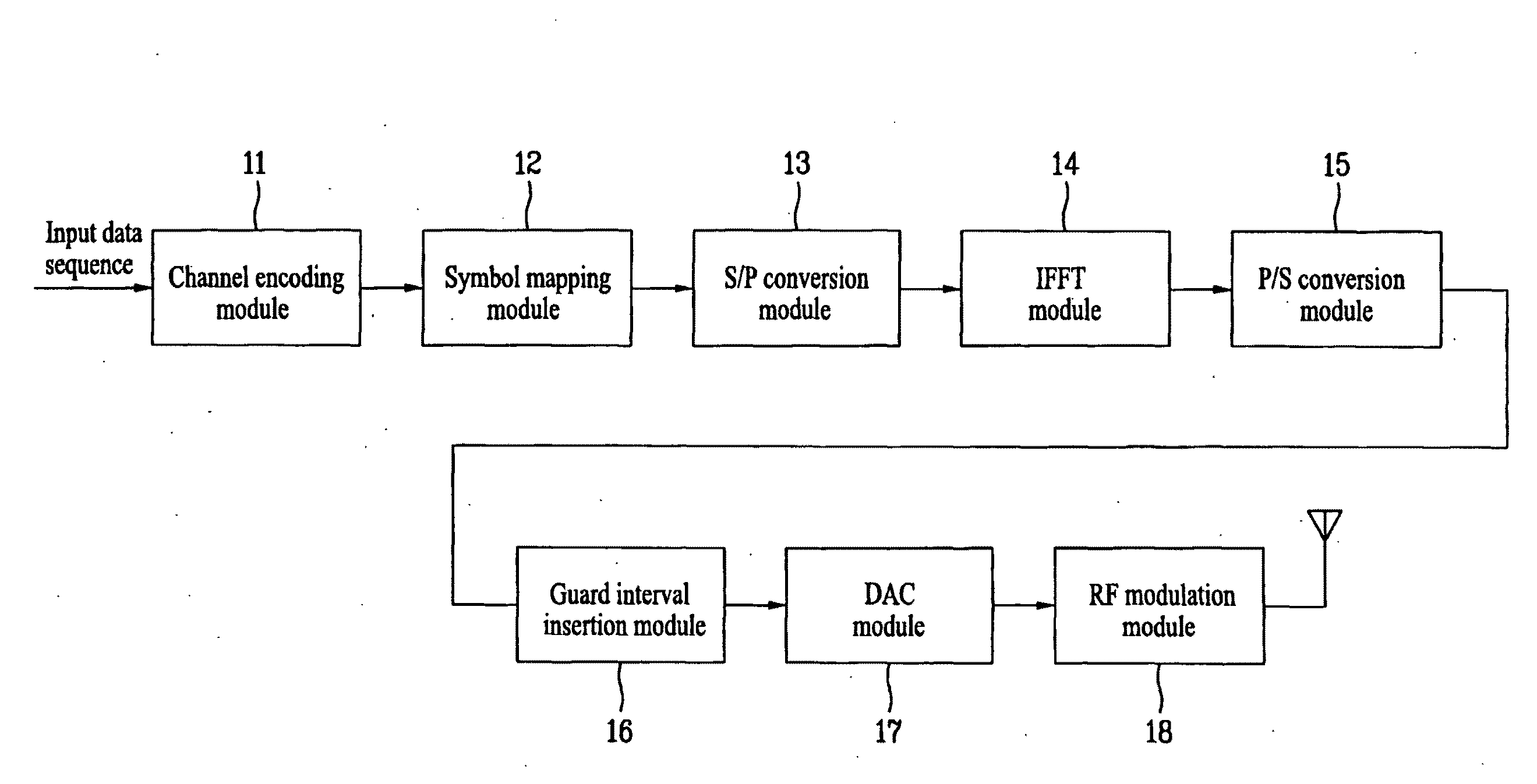
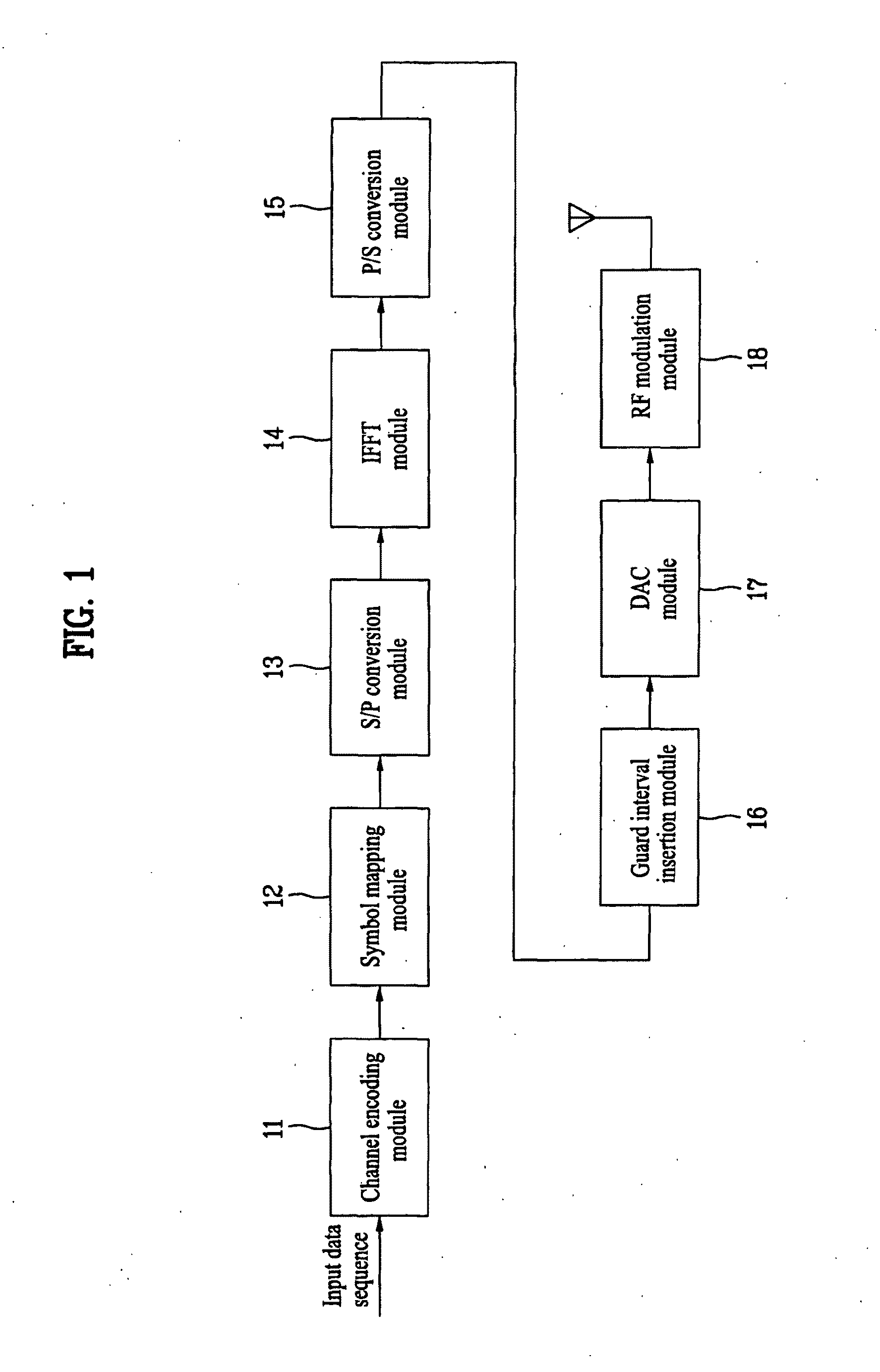
A method for transmitting / processing data in a wireless communication system, and a transmitter are disclosed. A method processing method for data transmission at a transmitting side of a wireless communication system employing multiple carriers comprises performing a symbol mapping process on a binary data sequence, and generating a symbol sequence, converting the symbol sequence into a time-domain symbol using a plurality of sub-carriers having a variable sub-carrier spacing therebetween, and adding a cyclic prefix to the time-domain symbol.

Description

TECHNICAL FIELD[0001]The present invention relates to a wireless communication system, and more particularly to a method for transmitting / processing data in a wireless communication system, and a transmitter.BACKGROUND ART[0002]Time dispersive characteristics (also called “delay spread characteristics”) between sub-carriers in a mobile communication system employing a plurality of sub-carriers have been determined according to communication environments of a cell managed by a base station (i.e., Node-B). For example, a large amount of time delay occurs in an urban district whereas a small amount of time delay occurs in a vast expanse of land. However, frequency dispersive characteristics (also called “Doppler spread”) between sub-carriers depend on a channel variation affected by a speed between a transmitter and a receiver.[0003]A representative example of the mobile communication system employing a plurality of sub-carriers is an Orthogonal Frequency Division Multiplexing (OFDM) s...

Claims


Application Information

Patent Timeline
IPC IPC(8): H04J9/00H04W4/00H04J4/00
CPCH04L5/0007H04L27/2602H04L5/0092H04L27/26035H04L27/26025H04L27/26
Inventor LEE, WOOK BONGIHM, BIN CHULLEE, MOON ILKO, HYUN SOOPARK, SUNG HO
Owner LG ELECTRONICS INC
Learn More