Method for the Trigger Failure Detection of Bidirectional Forwarding Detection

a technology of bidirectional forwarding and failure detection, applied in the field of link detection technologies, can solve the problems of inability to deliver the bfd parameter to the detection module, the negotiation module is usually very busy, and the failure occurs on the link

Active Publication Date: 2010-06-17
HUAWEI TECH CO LTD
View PDF4 Cites 58 Cited by
  • Summary
  • Abstract
  • Description
  • Claims
  • Application Information

AI Technical Summary

Benefits of technology

[0045]It can be seen from the above technical solutions that, in the present invention, failure detection is started only after one side of a BFD session receives a first BFD packet sent from the opposite side. It can be avoided that a router misinforms a link failure due to the difference between delays needed by negotiation modules in routers of two parties of a BFD session to deliver BFD session parameters to detection modules. The invention further includes detecting whether a failure occurs on a forwarding engine of one side of a BFD session to avoid that one side of a BFD session initiates a malicious attack to make the attacked side misinform link failure.

Problems solved by technology

If a party does not receive a BFD packet from the opposite side within a time interval, it is regarded that a failure occurs on the link, so as to rapidly find a link failure.
Because the negotiation module usually bears tasks of many other BFD sessions, such as establishing, negotiating and routing, the negotiation module is usually very busy.
Therefore, the delay needed by the negotiation module to deliver the BFD parameter to the detection module is unpredictable.
Especially when a performance difference or load difference exists between the neighbors of a BFD session, the delay difference is more apparent.
When the delay reaches a value, it is inevitable that one side of the BFD session misinforms that a failure occurs on the link.
However, due to various causes, router B cannot deliver the BFD session parameter to the detection module in a long time.
Because a difference exists between delays needed by the negotiation modules in routers of the two parties of the BFD session to deliver BFD session parameters to the detection module, the router may misinform that failure occurs on the link during failure detection.

Method used


Image

  • Method for the Trigger Failure Detection of Bidirectional Forwarding Detection
  • Method for the Trigger Failure Detection of Bidirectional Forwarding Detection
  • Method for the Trigger Failure Detection of Bidirectional Forwarding Detection

Examples


Embodiment Construction

[0051]The core concept of the invention lies in that, after two parties of a bidirectional forwarding link establish a BFD session, one side of the BFD session sends a BFD packet to the opposite side and receives a BFD packet from the opposite side; and when one side of the BFD session receives a first BFD packet from the opposite side, it triggers failure detection.

[0052]To make the objects, technical solutions and advantages of the invention more apparent, the invention is now further illustrated in detail in conjunction with the drawings and preferred embodiments.

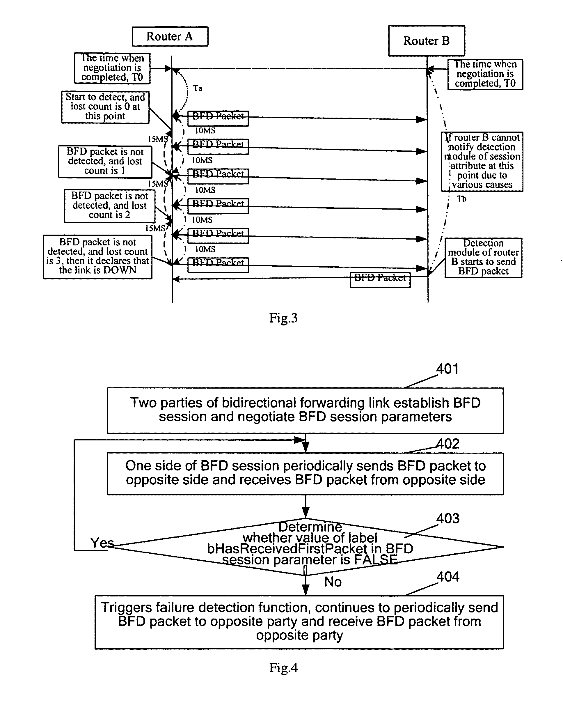
[0053]FIG. 4 is a flow chart of the method for triggering failure detection according to the invention. Taking as an example that the system for implementing BFD session detection is a router, as shown in FIG. 4, the method includes the following processes:

[0054]Process 401: The two parties of a bidirectional forwarding link establish a BFD session and negotiate BFD session parameters.

[0055]After the negotiation modules ...


PUM


Abstract

A method for failure detection on a bidirectional forwarding link mainly includes: sending, by one side of a BFD session, a BFD packet to the opposite side of the BFD session, and detecting a BFD packet sent by the opposite side, and starting, by the local side of the BFD session, BFD session detection when receiving a first BFD packet sent from the opposite side. By the method of the invention, it can be avoided that a router misinforms that failure occurs on a BFD session link due to difference of delays needed to deliver a BFD session parameter from a negotiation module of the router to a detection module.

Description

FIELD OF THE INVENTION[0001]The present invention relates to link detection technologies, and in particular, to a method for triggering failure detection in a Bidirectional Forwarding Detection.BACKGROUND OF THE INVENTION[0002]With the development of communication technologies, how to guarantee a quality of data transmission and how to rapidly locate a failure when a failure occurs on data transmission has become a problem urgent to be solved. Therefore, BFD, as a fast detection mechanism, emerges as the times require. In BFD, a link is detected by a rapid “Hello” mechanism with a rate that can be negotiated.[0003]BFD may be used for detecting the correctness of various types of transmission, including Ethernet, Multi-Protocol Label Switching (MPLS) Path, common routing encapsulation and IP network security protocol (IPSec) tunnel.[0004]BFD is developed from the basic transmission technology step by step, so with BFD, failure in each layer of a network may be detected. The object of...

Claims


Application Information

Patent Timeline
Patent Type & Authority Applications(United States)
IPC IPC(8): H04L12/26
CPCH04L45/28H04L45/02
Inventor TAN, XUEFEI
Owner HUAWEI TECH CO LTD
Why Eureka
Try Eureka