
Method of identification of a femtocell base station as a handover target, and apparatus therefor

a technology of femtocell base stations and target handovers, applied in the field of wireless telecommunications, can solve the problems of waste of network resources used in handover attempts to other femtocells than the one that is successful, and the availability of few primary scrambling codes (pscs), so as to reduce delays and block or drop calls.

Inactive Publication Date: 2010-06-17
WSOU INVESTMENTS LLC
View PDF4 Cites 48 Cited by
  • Summary
  • Abstract
  • Description
  • Claims
  • Application Information

AI Technical Summary

Benefits of technology

[0022]Preferred embodiments enable a neighbour femtocell base station to be uniquely identified for handover despite the Primary scrambling code “reuse” that occurs in femtocell base station deployments. This reduces the resources used in signalling as part of handover attempts to multiple neighbours, only one of which will be successful. Accordingly, in preferred embodiments, delays and blocked or dropped calls are reduced.
[0023]In some embodiments, where a femtocell base station can only handle a few calls at a time, the reduced chance of calls being blocked is particularly significant.

Problems solved by technology

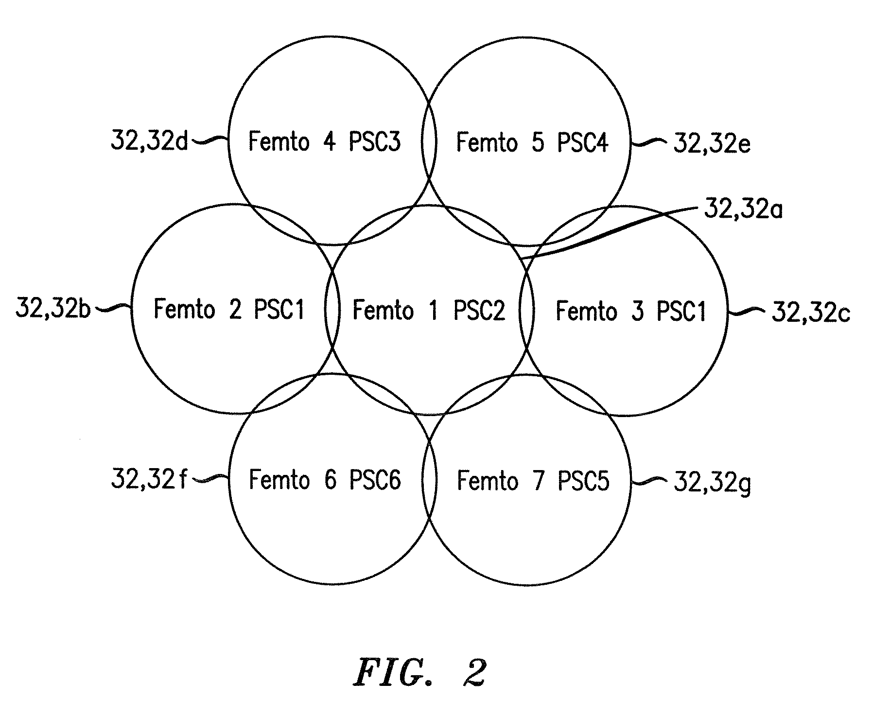
One problem of femtocell base stations, particular those involving code division multiple access, such as those in accordance with current Third Generation Partnership Project (3GPP) Universal Mobile Telecommunications System (UMTS) standards, is that there are few primary scrambling codes (PSCs) available.
This is inefficient because only one of the handover attempts is permitted to succeed.
Network resources that are used in the handover attempts to the other femtocells than the one that is successful, are wasted.

Method used


Image

  • Method of identification of a femtocell base station as a handover target, and apparatus therefor
  • Method of identification of a femtocell base station as a handover target, and apparatus therefor
  • Method of identification of a femtocell base station as a handover target, and apparatus therefor

Examples


Embodiment Construction

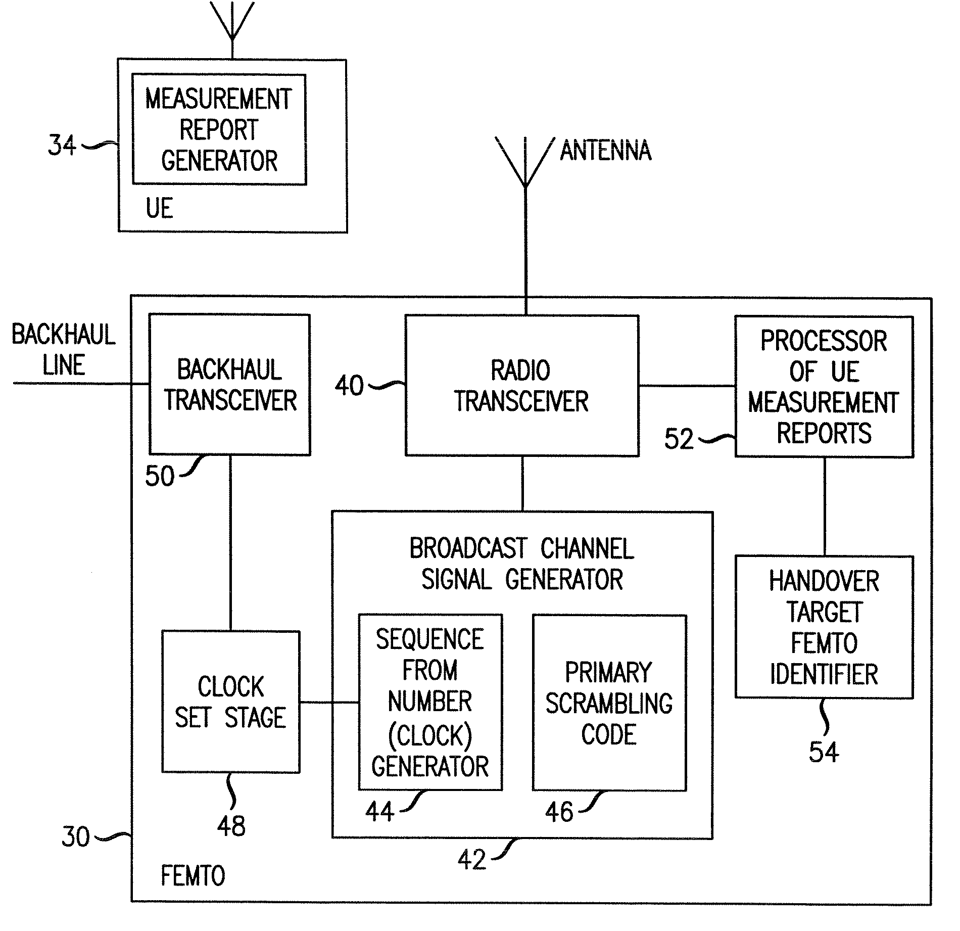
[0029]We now describe a network including femtocell base stations then look in greater detail at a femtocell base station and the relevant operation of the femtocell base station.

Network

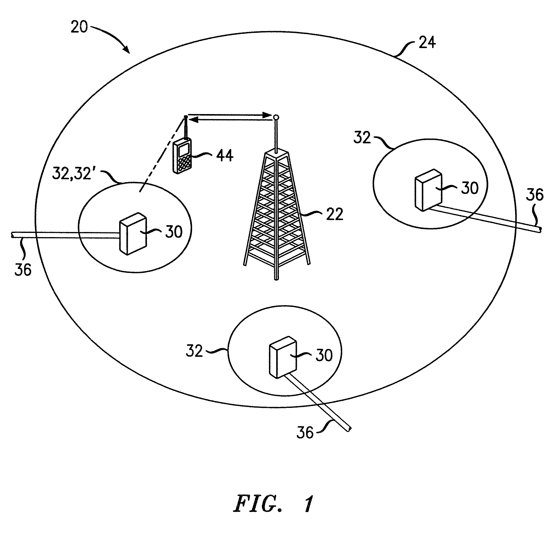
[0030]As shown in FIG. 1, in one communication network 20, there are two types of base stations (often denoted BS or BSs): macrocell base stations and femtocell base stations. One macrocell base station 22 for wireless telecommunications is shown for simplicity in FIG. 1. The macrocell base station has a radio coverage area 24 that is often referred to as a macrocell. The geographic extent of the macrocell 24 depends on the capabilities of the macrocell base station 22 and the surrounding geography.

[0031]Within the macrocell 24, each femtocell base station 30 provides wireless communications within a corresponding femtocell 32. A femtocell is a radio coverage area. The radio coverage area of the femtocell 32 is much less than that of the macrocell 24. For example, the femtocell 32 corresponds in size...


PUM


Abstract

A method is provided of identifying which one of a plurality of femtocell base stations neighbouring a first femtocell base station is to be the target for handover of a call connection with a user terminal from the first base station. The neighbour femtocell base stations use the same primary scrambling code as each other. The femtocell base stations use code-division multiple access, CDMA. Each of the neighbour femtocell base stations transmits a respective broadcast signal that include timing information such that each neighbour femtocell base station transmits a broadcast signal having different timing information to that of the other neighbour femtocell base stations. The user terminal receives broadcast signals, determines the timing information of at least one of the received broadcast signals and reports the timing information to the first femtocell base station. The first femtocell base station identifies the target femtocell base station for handover from the timing information.

Description

FIELD OF THE INVENTION[0001]The present invention relates to telecommunications, in particular to wireless telecommunications.DESCRIPTION OF THE RELATED ART[0002]Wireless telecommunications systems are well-known. Many such systems are cellular, in that radio coverage is provided by a bundle of radio coverage areas known as cells. A base station that provides radio coverage is located in each cell. Traditional base stations provide coverage in relatively large geographic areas and the corresponding cells are often referred to as macrocells.[0003]It is possible to establish smaller sized cells within a macrocell. Cells that are smaller than macrocells are sometimes referred to as microcells, picocells, or femtocells, but we use the term femtocells generically for cells that are smaller than macrocells. One way to establish a femtocell is to provide a femtocell base station that operates within a relatively limited range within the coverage area of a macrocell. One example of use of a...

Claims


Application Information

Patent Timeline
IPC IPC(8): H04W36/34
CPCH04W16/16H04W84/045H04W36/04H04W36/0083H04W36/0085H04W36/008375H04W36/00837
Inventor BRADLEY, NIGELCLAUSSEN, HOLGERSAPIANO, PHILIP CHARLES
Owner WSOU INVESTMENTS LLC
Learn More