Offshore oil production platform

a technology of oil production platform and oil tank, which is applied in the direction of underwater structures, artificial islands, hydroelectric engineering, etc., can solve the problems of increasing the cost and reliability of the platform, the difficulty of drilling,

Inactive Publication Date: 2010-06-17
NADARAJAH NAGENDRAN C +1
View PDF13 Cites 33 Cited by
  • Summary
  • Abstract
  • Description
  • Claims
  • Application Information

AI Technical Summary

Benefits of technology

[0009]The present invention relates to a first preferred embodiment of an offshore oil production platform being installed on sea bed comprising a deck, a base connected to at least one connecting leg substantially vertical upstanding from the base above the deck wherein the base includes at least one ballast chamber which is secured by connecting means to terminal end region of the at least one connecting leg wherein the ballast chamber includes at least one compartment for storing processed oil and gas, at least one ballast compartment to be filled with sea water or air or gas and at least one compartment for co

Problems solved by technology

Therefore, it is not possible at this depth to use gravity platforms resting on sea bed.
This mechanism has disadvantages as it needs to ensure exact lateral guidance of the deck as it is raised to a height above the water level, the reason that it needs to withstand high vertical loads due to the weight of the deck.
Besides that, this mechanism also leads to an increase of cost and reliability of the platform.
The deck is generally very heavy, which cannot be easily transferred from one place to another.
Other than ballasting, the deck can be raised or transferred by means of jacks but jacks are sensitive to lateral forces.
All the above mentioned platforms have a disadvantage when the oil in the well is in a depletion stage.
Most of the platforms are not moveable and re-useable at a new oil production site.
Another disadvantage is that the platforms are used for transpo

Method used


Image

  • Offshore oil production platform
  • Offshore oil production platform
  • Offshore oil production platform

Examples


Embodiment Construction

[0029]A detailed description of preferred embodiments of the invention is disclosed herein. It should be understood, however, that the disclosed preferred embodiments are merely exemplary of the invention, which may be embodied in various forms. Therefore, the details disclosed herein are not to be interpreted as limiting, but merely as the basis for the claims and for teaching one skilled in the art of the invention.

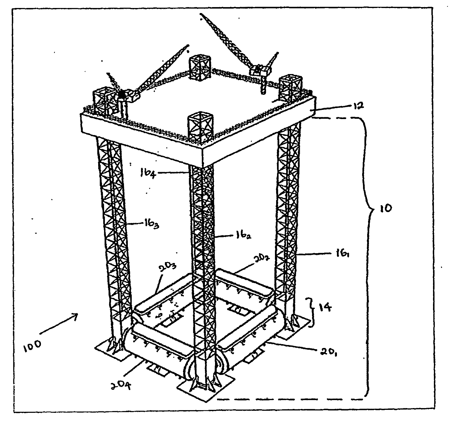
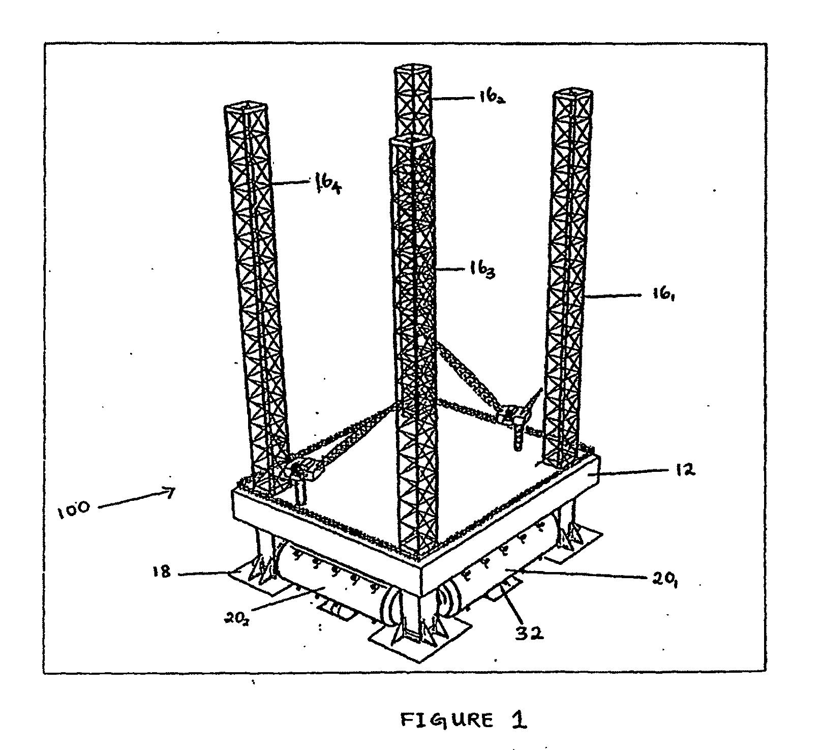
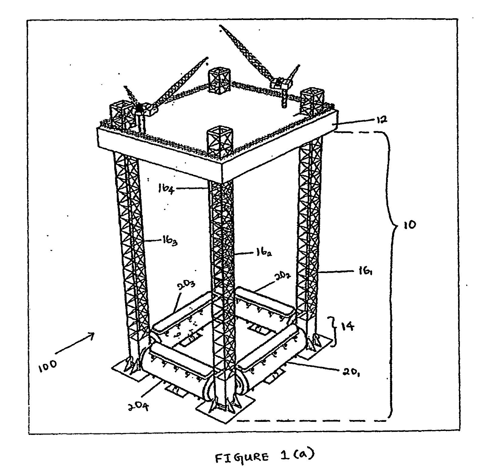
[0030]FIG. 1 is a diagrammatic view illustrating a first preferred embodiment of an offshore oil production platform before being towed to an oil extraction destination. The oil production platform includes a sub-structure (10) and a deck (12). The sub-structure (10) comprises a base (14) comprising with four ballast chambers (201), (202), (203), (204) connected to one terminal end region of four connecting legs (columns or jackets) (161), (162), (163), (164) respectively upstanding from the ballast chambers (20) to above the deck (12). The ballast chambers (20) connect...


PUM


Abstract

The present invention relates to an offshore oil production platform. The platform includes a deck (12) and a sub-structure (10) comprising plurality of ballast chambers (20) and at least one of connecting leg (16) connected from the ballast chambers (20) to the deck (12). The ballast chambers (20) include at least one oil storage compartment (22), at least one ballast compartment (24) and at least one air pressure compartment (26). The oil and gas storage compartment (22) is for storing processed oil and gas. During installation of the platform, the ballast chambers (20) are ballasted with sea water (46) which allows lowering of the connecting legs (16) towards the sea bed (34). After the ballast chambers (20) reach the sea bed (34), locking means is actuated to a locked position to prevent movement of the sub-structure (10) of the platform. The deck (12) is moved up to a predetermined height from sea level by jacking means. After the oil is extracted, it is then processed and separated to processed oil and gas. The processed oil and gas are then stored in the oil and gas storage compartment (22). The oil and gas are then transferred to a buoy and then loaded to tanker vessels by connecting conduits. During the de-installation of the oil production platform, the ballast chambers (20) are de-ballasted whereby the sea water (46) in the ballast compartment (24) is flushed out. Thus, the sub-structure (10) of the platform moves upwards to reach the deck (12). When the base (14) touches the deck (12), the locking means is actuated thereby locking the sub-structure (10) together with the deck (12). Finally, the oil production platform is towed to its new destination for further extraction of oil.

Description

FIELD OF INVENTION[0001]The present invention relates to an oil production platform. More particularly, the invention relates to an offshore oil production platform which includes a deck extending above the level of sea and connected to a lower base with connecting legs extending substantially vertically. The present invention also relates to a method of installing and de-installing the oil production platform.BACKGROUND ART[0002]Offshore oil production platforms generally include a deck carrying production equipments necessary for drilling, technical buildings and crew quarters, storage for storing petroleum products extracted from offshore oil fields and other requirements for production of oil and gas. Currently, there is a great interest in operating offshore oil fields at great depths, from several hundred meters to thousand meters or more. Therefore, it is not possible at this depth to use gravity platforms resting on sea bed. At great depths, semi-submersible platforms can be...

Claims


Application Information

Patent Timeline
IPC IPC(8): E02B17/08E02B17/02E02D29/00
CPCE02B17/00E02B17/021E02B17/025E02B2017/0047E02B2017/0086E02B2017/006E02B2017/0069E02B2017/0082E02B2017/0052
Inventor NADARAJAH, NAGENDRAN C.DE RAJ, RENATA ANITA
Owner NADARAJAH NAGENDRAN C
Why Eureka
Try Eureka