Footwear
a technology for soles and shoes, applied in the field of shoes, can solve the problems of inadequate distribution of the effect, incomplete benefit of the spring effect, and inability to meet all the expected functions so as to increase the spring effect of the sole assembly, improve the damping, and lengthen the bridge
- Summary
- Abstract
- Description
- Claims
- Application Information
AI Technical Summary
Benefits of technology
Problems solved by technology
Method used
Image
Examples
first embodiment
[0033]The first embodiment, which is described hereinafter, relates more particularly to shoes for walking or running on flat or uneven terrain. However, the invention applies to other fields, such as those mentioned hereinabove.
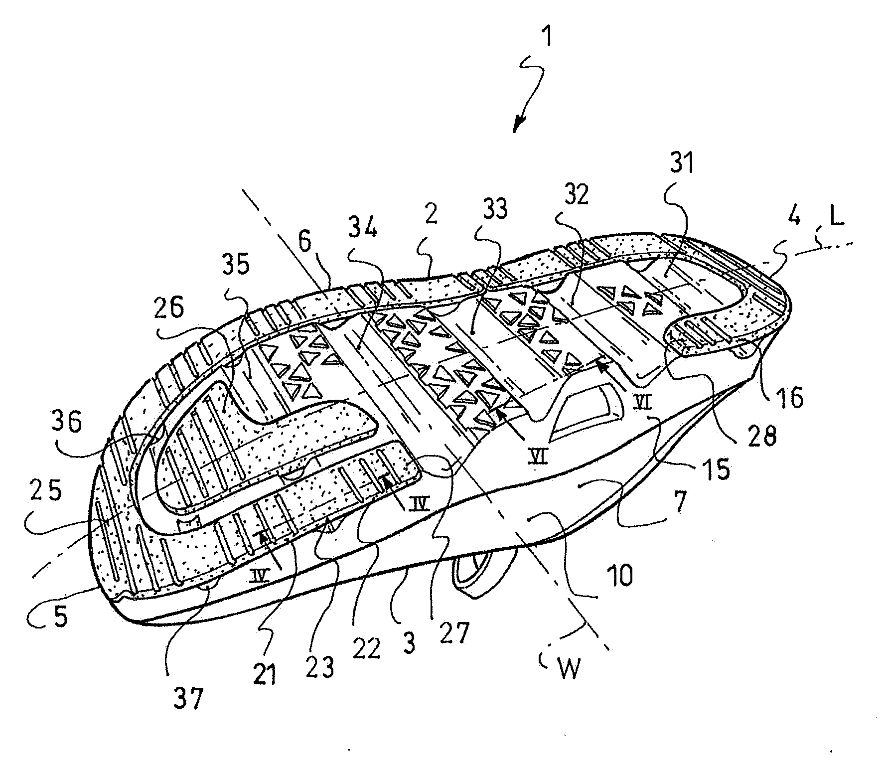
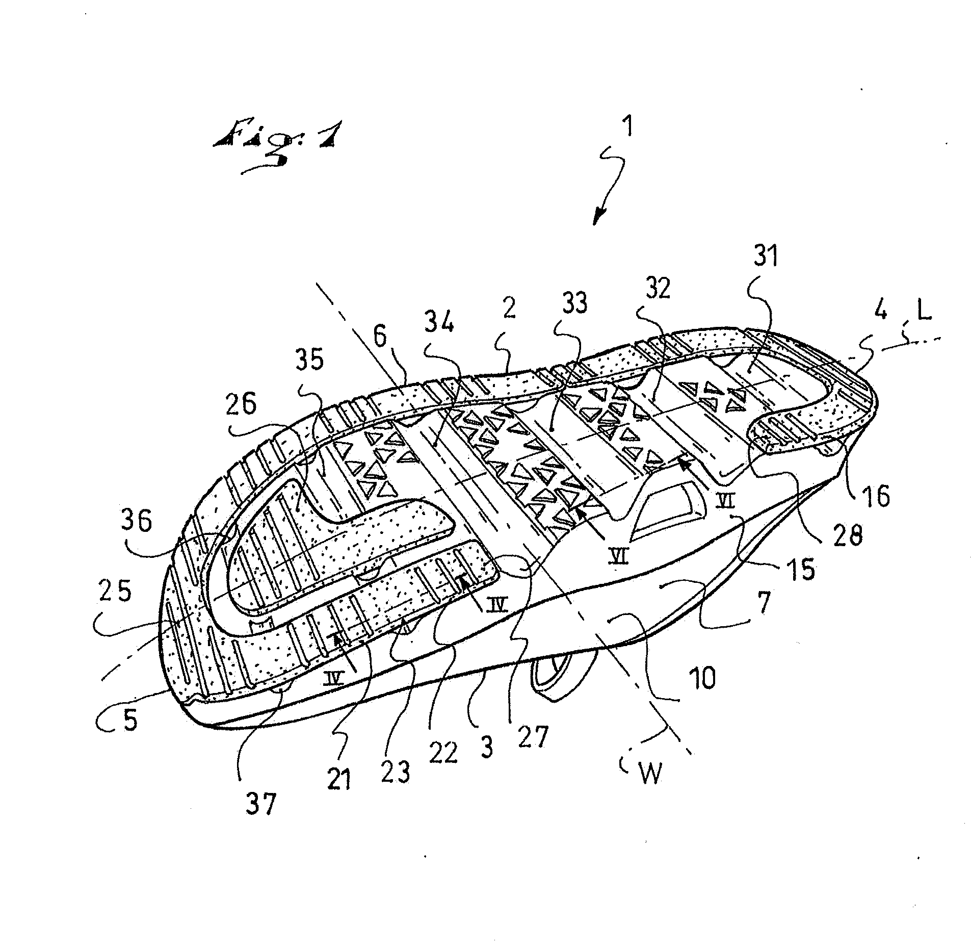
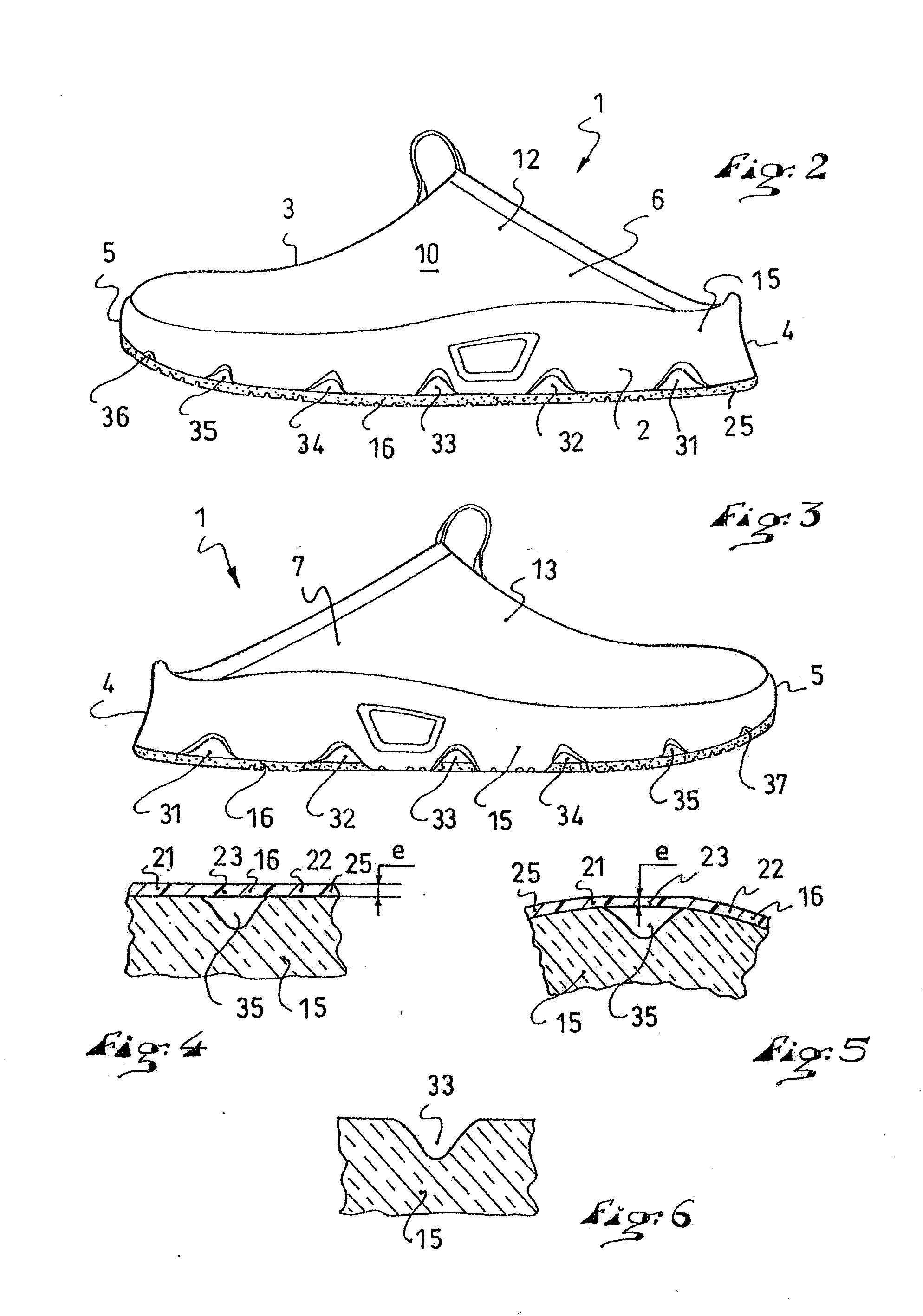
[0034]The first embodiment is described hereinafter with reference to FIGS. 1 to 6.
[0035]As shown in FIG. 1, a walking shoe is provided to receive the user's foot.
[0036]In a known manner, the shoe 1 includes an outer sole assembly 2 and an upper 3 arranged on the sole assembly. The shoe 1 extends lengthwise along a longitudinal direction L, between a rear end 4, or heel, and a front end 5, or tip, and widthwise along a transverse direction W, between a lateral side 6 and a medial side 7.
[0037]As shown, the upper 3 includes a lower portion 10 that is provided to surround the foot but does not include an upper portion that might extend up to and / or beyond the ankle. However, the upper could also be provided to include an upper portion.
[0038]According to the fi...
third embodiment
[0069]The third embodiment is illustrated in FIG. 8. Still in the same context, the sole assembly 2 of a shoe 1 includes a first comfort layer 15 and a reinforcement layer 16.
[0070]What is specific to the third embodiment is the structure of the reinforcement layer 16. The reinforcement layer includes a single S-shaped piece 55. This piece 55, or S-shape, extends from a first end 57 to a second end 58. Each end 57, 58 is located in the area of an opposite side of the shoe. In a non-limiting fashion, the first end 57 is located on the lateral side 6, whereas the second end 58 is located on the medial side 7. The reverse arrangement is also encompassed by the invention.
[0071]The first end 57 is located in the area of the metatarsus, i.e., spaced from the tip 5. Similarly, the second end is located in an area spaced from the heel 4. To form the S-shape, the piece 55 edges, or borders, the tip 5 from the lateral side 6 to the medial side 7, extends diagonally from the medial side 7 to t...
fourth embodiment
[0073]The fourth embodiment is illustrated in FIG. 9. The sole assembly 2 of the shoe 1 still includes a first comfort layer 15 and a reinforcement layer 16.
[0074]What is specific to the fourth embodiment is once again the structure of the reinforcement layer 16. The latter includes a single lengthened and curved piece 65. This piece 65 extends from the heel 4 to the 5. The piece 65 is centered between the sides 6, 7 towards the heel 4, so as to extend closer to the medial side 7 as it extends toward the tip 5. This structure and arrangement is well-suited for a flat foot rolling movement of the sole assembly 2.
[0075]Moreover, some cavities, for example the three cavities 31, 32, 33 are oriented along the transverse direction W, whereas other cavities, for example the three cavities 34, 35, 36, together with the transverse direction W, form an angle that is comprised between 5° and 30°. Thus, at least one cavity is a groove which, together with the transverse direction W of the shoe...
PUM
| Property | Measurement | Unit |
|---|---|---|
| angle | aaaaa | aaaaa |
| angle | aaaaa | aaaaa |
| thickness | aaaaa | aaaaa |
Abstract
Description
Claims
Application Information
 - R&D
- Intellectual Property
- Life Sciences
- Materials
- Tech Scout
- Unparalleled Data Quality
- Higher Quality Content
- 60% Fewer Hallucinations
Browse by: Latest US Patents, China's latest patents, Technical Efficacy Thesaurus, Application Domain, Technology Topic, Popular Technical Reports.
© 2025 PatSnap. All rights reserved.Legal|Privacy policy|Modern Slavery Act Transparency Statement|Sitemap|About US| Contact US: help@patsnap.com


