Brake actuator and method of forming the same

a diaphragm-type, brake actuator technology, applied in the direction of brake cylinders, braking systems, machines/engines, etc., can solve the problems of negative impact on the lifespan of the brake actuator of the kind, formation of corrosion cells, anodic metal corrosion, etc., to reduce frictional engagement, improve surface configuration, and eliminate corrosion potential

Active Publication Date: 2010-06-24
INDIAN HEAD INDUSTRIES INC
View PDF6 Cites 11 Cited by
  • Summary
  • Abstract
  • Description
  • Claims
  • Application Information

AI Technical Summary

Benefits of technology

[0018]An advantage of the present invention is to provide an improved spring guide that provides corrosion isolation, whereby the spring guide is fabricated from glass filled nylon material to insulate the spring from the head or cover of the brake actuator thereby eliminating the corrosion potential resulting from dissimilar metals are in direct contact with each other such as when the spring contacts the inner wall of the head.
[0019]Another advantage of the present invention is to provide an improved spring guide that provides improved surface configuration to house the spring inside the head thereby reducing the frictional engagement between the inner wall of the head and the spring to eliminate formation of a corrosion cell and improve lifespan of the spring.
[0020]Still another advantage of the present invention is to provide an improved spring guide configuration presenting a flange portion extending beyond the radius of the spring to prevent damage caused to the protective coating on the spring coil when the coil from rolls off the edge of the spring guide and contacting the inner wall of the head.
[0021]Other advantages and meritorious features of the improved brake actuator of this invention will be more fully understood from the following description of the preferred embodiment, the appended claims, and the drawings; a brief description of which follows.

Problems solved by technology

When the pressure in the pneumatic chamber falls below a predetermined minimum, which may occur as a result of a failure of the pneumatic braking system of the vehicle, the power spring expands, driving the pushrod through the opening in the web portion of the flange case, actuating the vehicle braking system.
A problem with any prior art diaphragm-type brake actuator is formation of a corrosion cell, which negatively impacts lifespan of the brake actuators of the kind.
This leads to the anodic metal corroding more quickly thereby resulting in formation of the corrosion cell.
The presence of electrolyte and conducting path between the metals cause corrosion where otherwise neither metal, if used alone, would have been corroded.

Method used


Image

  • Brake actuator and method of forming the same
  • Brake actuator and method of forming the same
  • Brake actuator and method of forming the same

Examples


Embodiment Construction

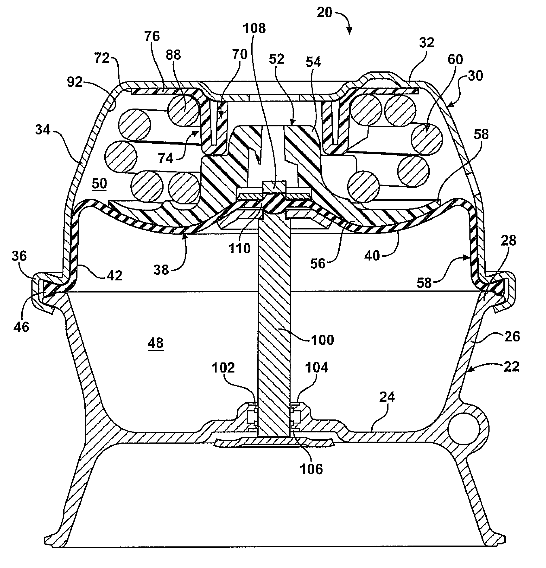
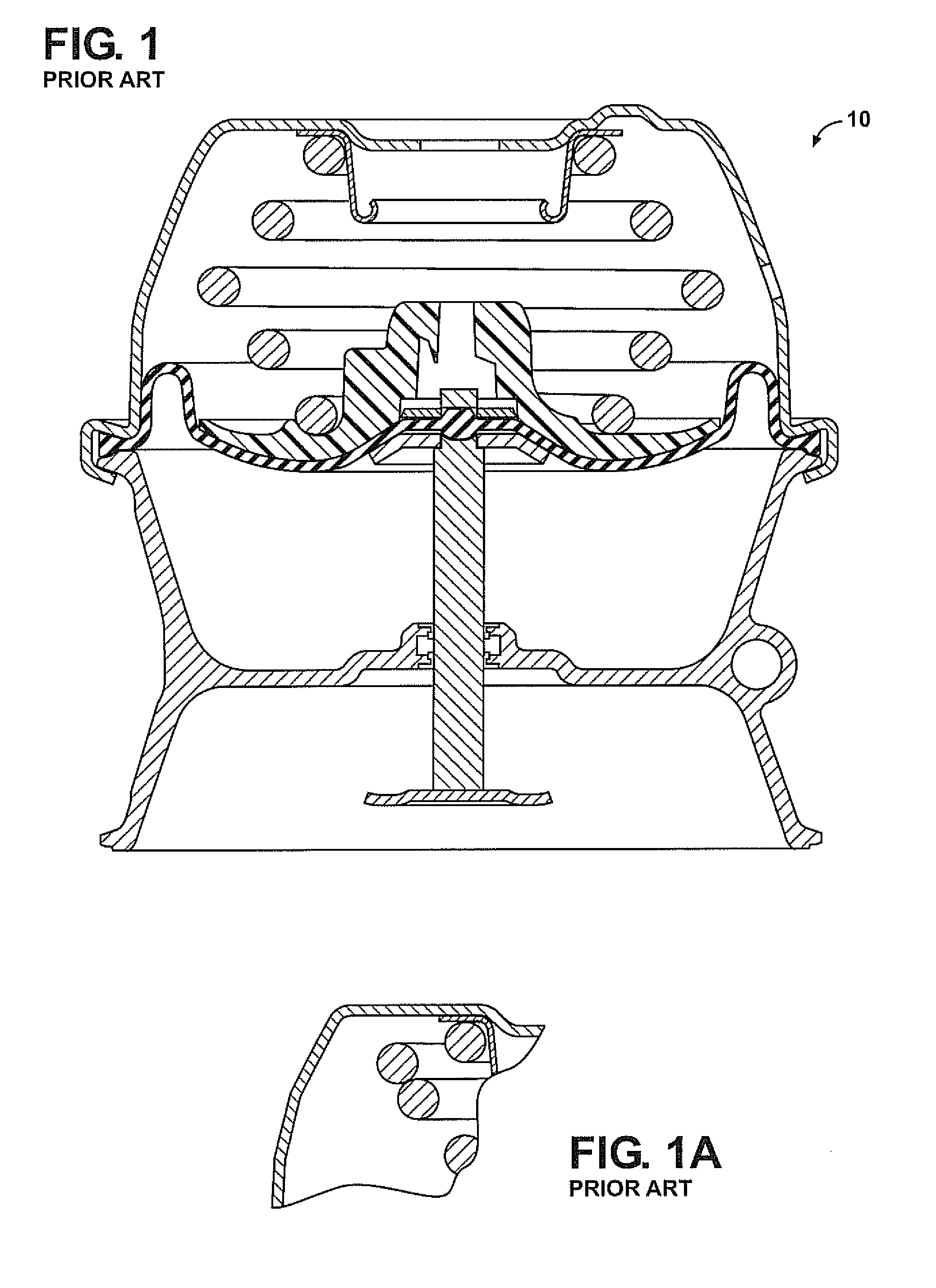
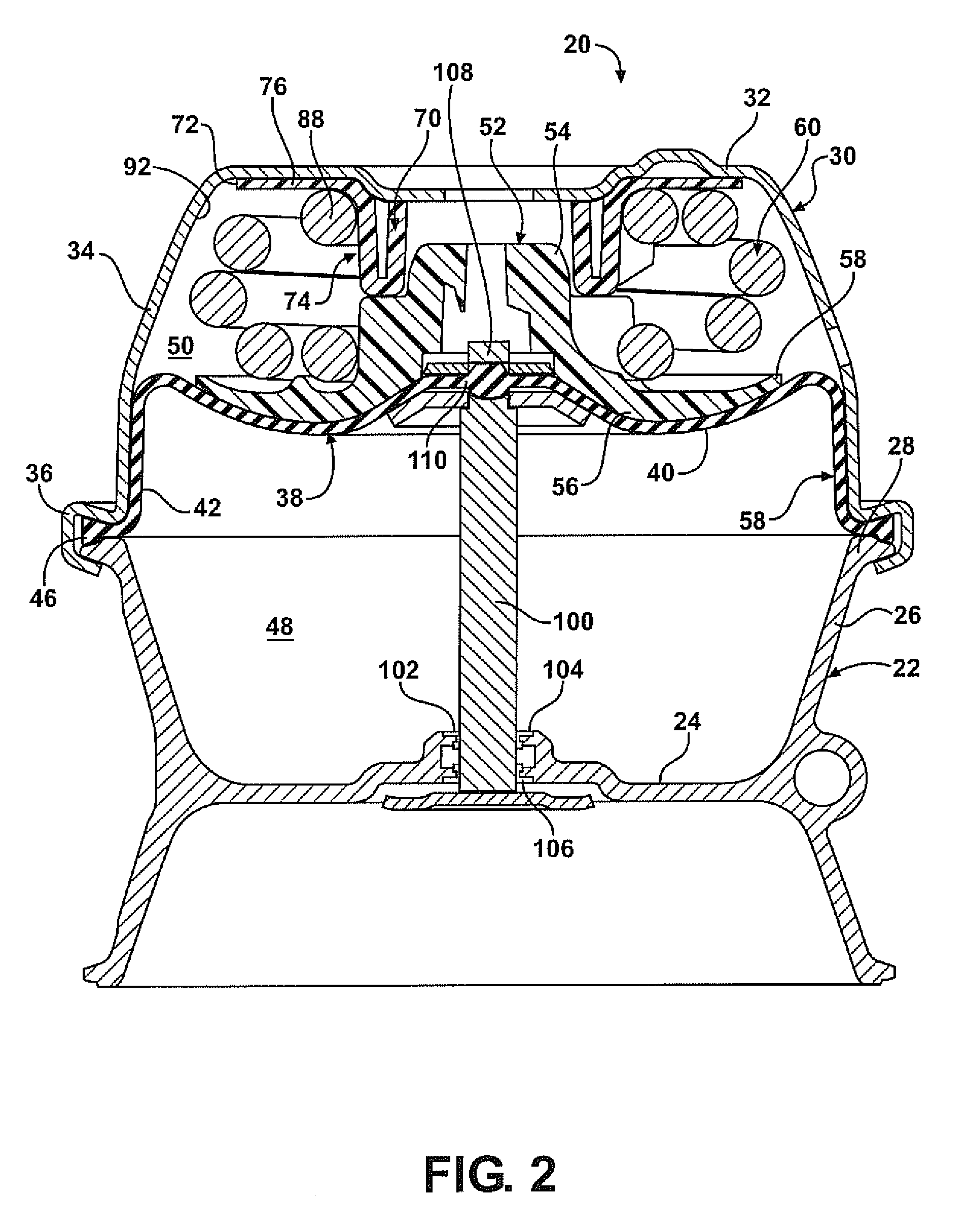
[0030]Referring to the Figures, wherein like numerals indicate like or corresponding parts, a prior art brake actuator is generally shown at 10 in FIG. 1. FIG. 2 illustrates an inventive brake actuator, generally shown at 20. As set forth above, and illustrated in FIG. 2, the spring brake actuator 20 includes a generally H-shaped flange case, generally indicated at 22, having a central web portion 24, an outer wall 26 and a radially extending flange 28. A cover or head portion, generally indicated at 30, of the brake actuator 20 includes an end wall 32, a side wall 34 and a flange or skirt portion 36. The brake actuator 20 further includes a flexible diaphragm 38 having a central portion 40, a side wall portion 42 and a radially extending rim portion 46. The flexible diaphragm 38 extends between the flange case 22 and the cover 30 forming a lower pneumatic chamber 48 and an upper pneumatic chamber 50 on opposed sides of the diaphragm 38.

[0031]The brake actuator 20 further includes a...


PUM


Abstract

An improved diaphragm-type pneumatic brake actuator includes a flange case, a cover cooperable with the flange case, a flexible diaphragm extending between the flange case and the cover forming a lower pneumatic chamber and an upper pneumatic chamber on opposed sides of the diaphragm. A piston assembly is disposed in the cover for moving a spring between compressed and decompressed positions. A spring guide is disposed between the cover and the piston assembly in the upper chamber. The spring guide prevents direct contact of the spring with the cover to prevent formation of a corrosion cell.

Description

FIELD OF THE INVENTION[0001]The present invention relates to an improved diaphragm-type pneumatic brake actuator for vehicle braking systems.BACKGROUND OF THE INVENTION[0002]Pneumatic brake actuators form part of the pneumatic braking system of commercial vehicles having a large gross vehicle weight, including trucks, buses and trailers requiring a braking system which responds rapidly with substantial braking power. A typical diaphragm-type pneumatic brake actuator includes a housing having cup-shaped housing members including opposed rim or flange portions, a flexible diaphragm which is cup-shaped in its relaxed condition including a central portion, a generally conical side wall which surrounds the central portion and a generally radial rim portion which extends between the rim portions of the housing members. A brake actuator further includes a piston having a contact surface which engages the central portion of the diaphragm and which reciprocates with the central and side wall...

Claims


Application Information

Patent Timeline
Patent Type & Authority Applications(United States)
IPC IPC(8): B60T17/08
CPCB60T17/083
Inventor PRAGER, CHRISTOPHER J.SPRAGUE, GARY R.ABDALLAH, MOHAMMED
Owner INDIAN HEAD INDUSTRIES INC
Why Eureka
Try Eureka