Vaporized fuel processing device and method

Inactive Publication Date: 2010-06-24
MAHLE FILTER SYST JAPAN CORP
View PDF6 Cites 7 Cited by
  • Summary
  • Abstract
  • Description
  • Claims
  • Application Information

AI Technical Summary

Benefits of technology

[0006]It should, herein, be noted that a heat quantity deprived from the adsorption material during the purge of the fuel becomes larger, as the purge air quantity to be introduced into the canister becomes larger and, in other words, as the fuel purged from the adsorption material becomes increased. It is desirable to set an electric power to be supplied to the electric heater to obtain a sufficient quantity of heat. However, if the above-described setting is carried out in the technique disclosed in the above-identified Japanese Utility Model Registration Application Publication, a relatively large power is supplied to the electric heater even when the

Problems solved by technology

However, if the above-described setting is carried out in the technique disclosed in the above-identified Japanese Utility Model Registration Application Publication, a relatively large power is supplied to the electric heater even when the purge air quantity is small.
There are possibilities that a consumed electric power becomes increased, a vehicular battery becomes overloaded, and a life of the previously proposed vaporized fuel processing dev

Method used


Image

  • Vaporized fuel processing device and method
  • Vaporized fuel processing device and method
  • Vaporized fuel processing device and method

Examples


Embodiment Construction

[0014]Reference will hereinafter be made to the drawings in order to facilitate a better understanding of the present invention.

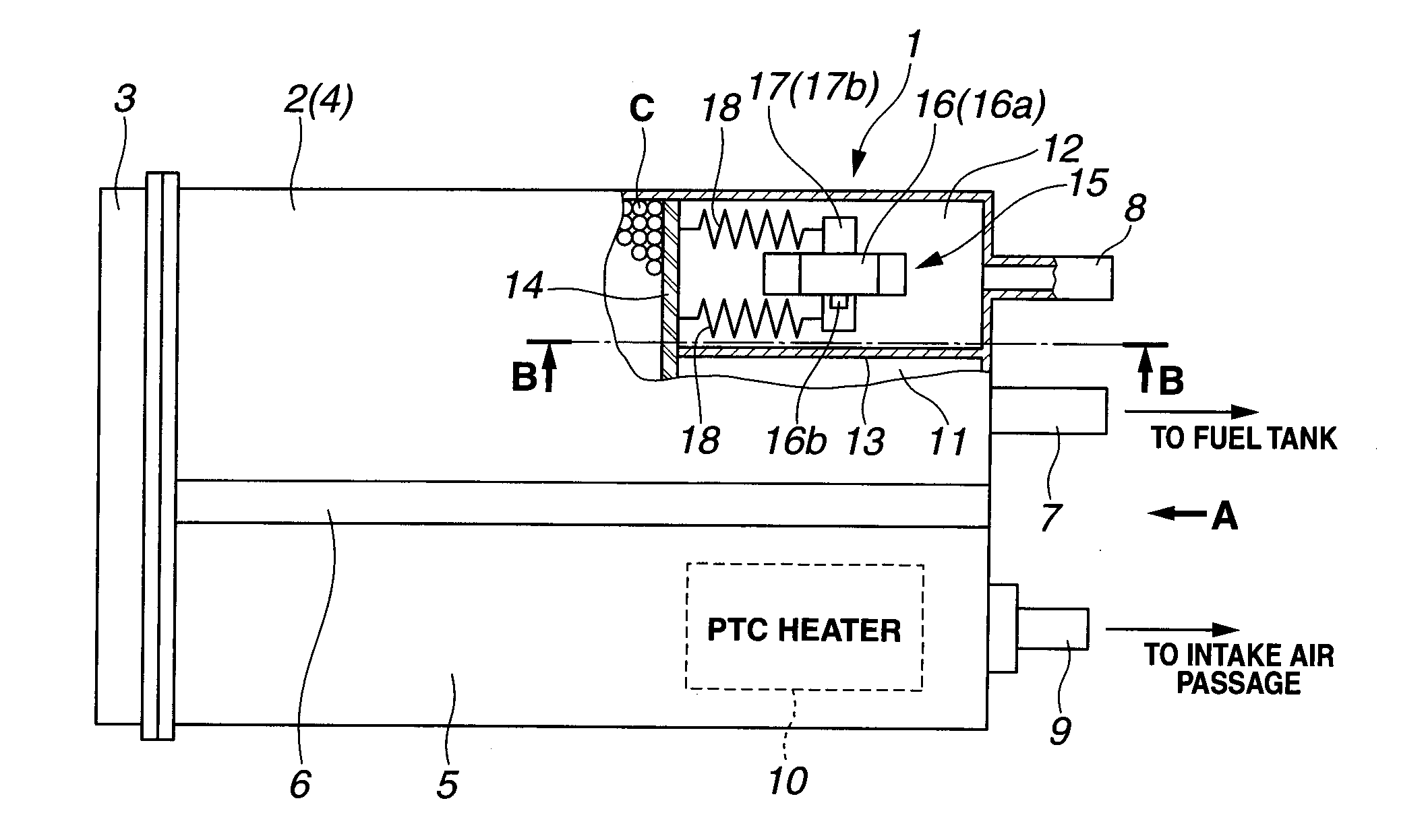
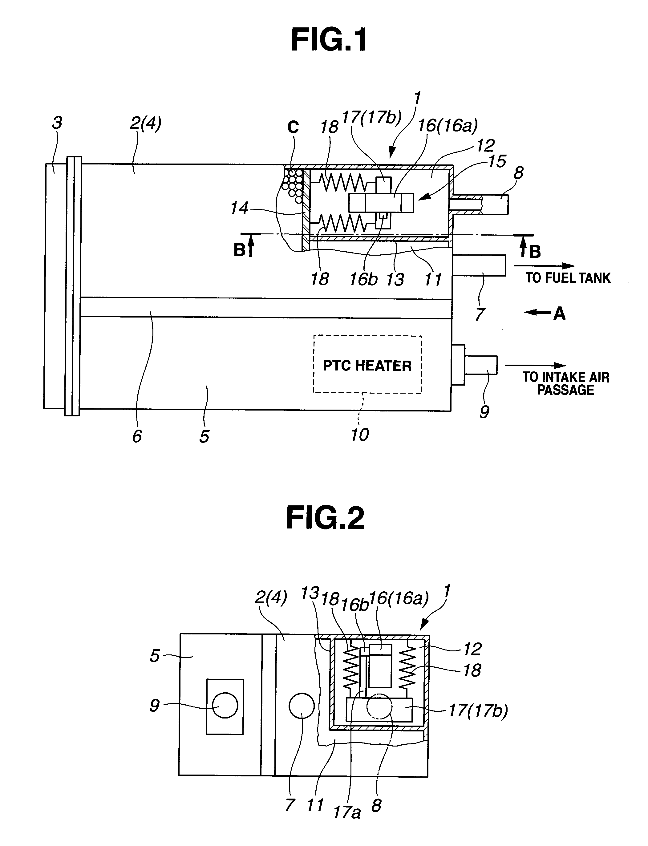
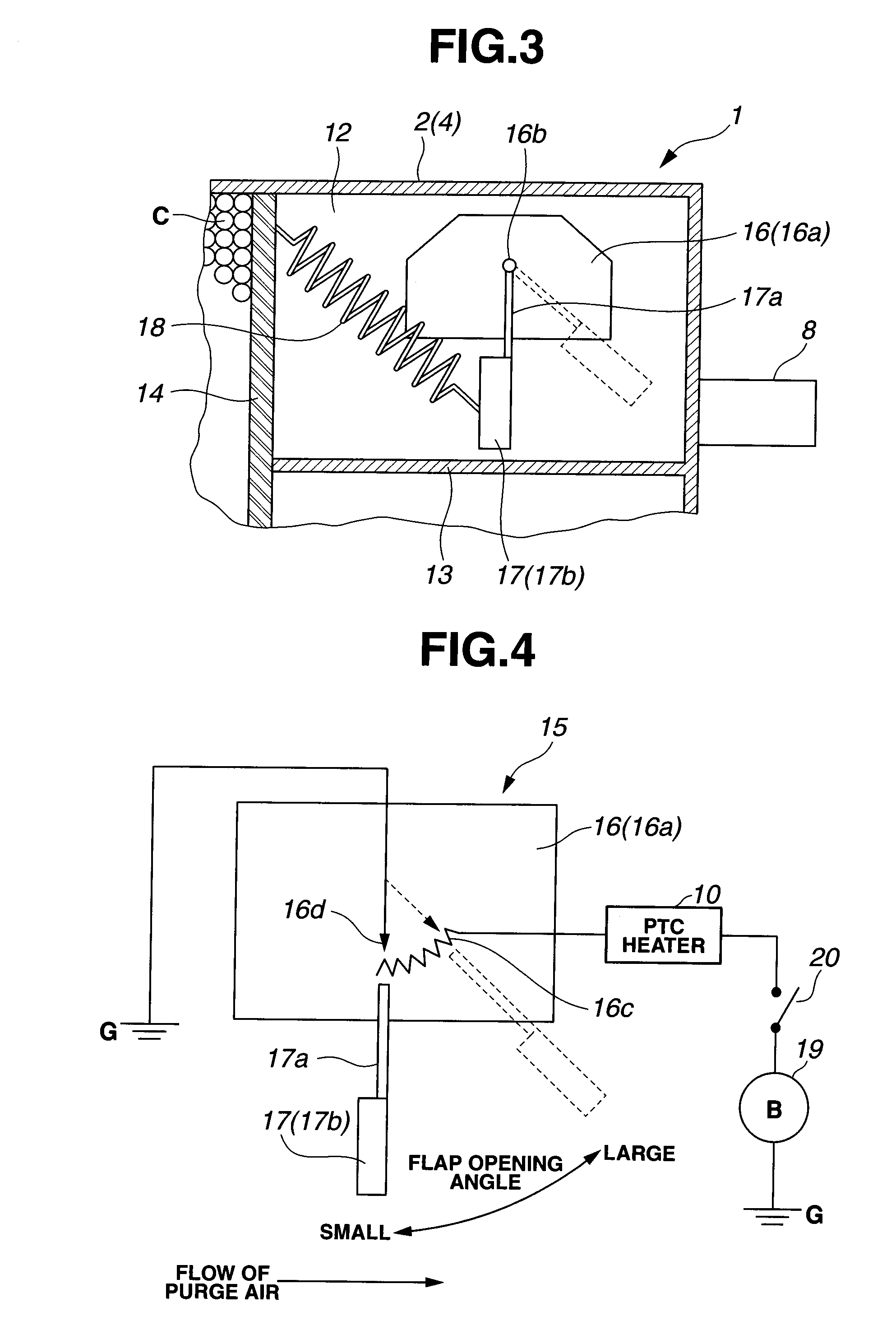
[0015]FIGS. 1, 2, 3, and 4 show a preferred embodiment of a vaporized fuel processing device according to the present invention. FIG. 1 shows a partially cut plan view of a canister in the vaporized fuel processing device according to the present invention. FIG. 2 shows an arrow marked A directional view shown in FIG. 1. FIG. 3 shows a cross sectional view cut away along a line of A in FIG. 1. FIG. 3 shows a cross sectional view cut away along a line of B-B shown in FIG. 1.

[0016]As shown in FIGS. 1 through 3, canister 1 of the vaporized fuel processing device according to the present invention is depicted. Canister 1 includes a canister main body 2 in which an activated carbon C which is an adsorption material is stored; and an encapsulation 3 which closes an opening end of canister main body 2. It should be noted that canister main body 2 and encapsulation...


PUM


Abstract

In vaporized fuel processing device and method, an adsorption material provides a canister and configured to once hold the vaporized fuel generated in a fuel tank into the adsorption material within the canister, the canister into which an intake air pressure of an engine used for purge air being introduced when the engine is operated and purge air purging fuel corresponding to vaporized fuel from the adsorption material to be supplied to the engine; an electric heater configured to variably control an electric power supplied to the heater in accordance with a purge air quantity to be introduced within the canister.

Description

BACKGROUND OF THE INVENTION[0001](1) Field of the Invention[0002]The present invention relates to vaporized fuel processing device and method which temporarily hold vaporized fuel generated in a fuel tank by means of an adsorption material installed within a canister, to supply vaporized fuel into an engine by purging the fuel corresponding to the vaporized fuel from the adsorption material during an operation of an engine, and, particularly, relates to the vaporized fuel processing device and method which can achieve an improvement in an efficiency of the engine.[0003](2) Description of Related Art[0004]In such a kind of vaporized fuel processing devices as described above, a purge air is introduced into the canister through an intake air negative pressure of the engine. The purge air purges a fuel held on the adsorption material so that a latent heat of an evaporation causes the material to be cooled. Then, the fuel becomes difficult to be purged from the adsorption material. To a...

Claims


Application Information

Patent Timeline
IPC IPC(8): F02M33/06
CPCF02M25/0854F02D41/003F02M2025/0881F02M25/089
Inventor ICHIKAWA, TAKASHINAKANO, MASARU
Owner MAHLE FILTER SYST JAPAN CORP
Why Eureka
Try Eureka