Electric working machine

A working machine, electric technology, applied in the direction of electric vehicles, current collectors, electrical components, etc., can solve problems such as time lag, impossible communication between electric working machines and external equipment, and reduced sense of use

Pending Publication Date: 2020-10-23
MAKITA CORP
View PDF1 Cites 0 Cited by
  • Summary
  • Abstract
  • Description
  • Claims
  • Application Information

AI Technical Summary

Problems solved by technology

[0003] In addition, when the power supply of the power supply for the control unit is cut off, the following phenomenon may occur: (1) communication between the electric working machine and external equipment becomes impossible when the power supply is cut off, and (2) the trigger There is a time lag between the re-operating of the device and the operation of the motor, resulting in a decrease in usability

Method used


Image

  • Electric working machine
  • Electric working machine
  • Electric working machine

Examples


no. 1 approach

[0058] [1-1. Overall structure]

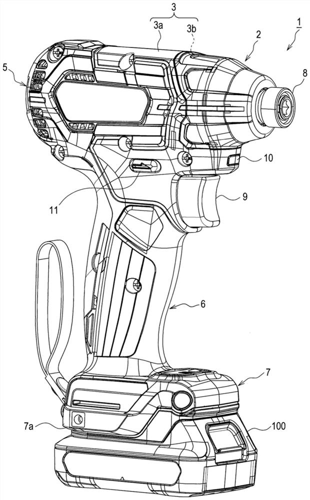
[0059] figure 1 The illustrated electric working machine 1 is configured as a cordless hammer drill, for example. The cordless hammer drill is driven by electric power supplied from the battery pack 100 described later. The cordless hammer drill is used, for example, to rotate fastening components such as screws and bolts. The cordless hammer drill is configured to apply an impact in the rotation direction according to the load when the fastening member is rotated, and thereby can generate a large torque in the rotation direction.

[0060] Such as figure 1 As shown, the electric working machine 1 of this embodiment includes a main body 2 and a battery pack 100. The battery pack 100 is configured to be detachable from the main body 2.

[0061] The main body 2 includes a housing 3. The housing 3 is provided with two split housings 3a, 3b divided into left and right, and is constructed by combining these split housings 3a, 3b. The housing 3 may be ...

no. 2 approach

[0117] As a second embodiment, a second electric working machine 21 constructed by replacing a part of the constituent elements of the electric working machine 1 of the above-mentioned embodiment (hereinafter also referred to as the first embodiment) will be described.

[0118] Such as Figure 4 As shown, the second electric working machine 21 is configured by replacing the power supply 64 for the control unit, the motor 61, and the motor drive unit 63 in the electric working machine 1 with the power supply 91 for the second control unit, the brushless motor 97, and the motor driver, respectively. 99.

[0119] [2-1. Power supply for the second control unit]

[0120] The power supply 91 for the second control unit is configured to include a third conversion power supply 93 and a fourth conversion power supply 95 instead of the first conversion power supply 65 in the power supply 64 for the control unit.

[0121] The third conversion power source 93 includes a DC-DC converter that conve...

no. 3 approach

[0145] As a third embodiment, a third electric working machine 23 constructed by substituting some constituent elements in the second electric working machine 21 of the second embodiment will be described.

[0146] Such as Image 6 As shown, the third electric working machine 23 is configured to replace the power supply 91 for the second control unit in the second electric working machine 21 with the power supply 111 for the third control unit.

[0147] [3-1. Power supply for the third control unit]

[0148] The third control unit uses the power supply 111 to voltage-convert the battery voltage VB from the battery pack 100 and outputs the voltage-converted constant voltage Vcc to the constant voltage supply line 81. The constant voltage Vcc is supplied to each part (control unit 62 and the like) of the third electric working machine 23 via the constant voltage supply line 81. In the third embodiment, the constant voltage Vcc is 5V. The power supplied from the third control unit pow...


PUM


Abstract

The invention provides an electric working machine which can reduce power consumption when the electric working machine is not used. The electric working machine in one aspect of the present disclosure includes a driving device using power from a power source for driving, a controller, a control power source, and an operation state determiner. The control power source includes a first convertion power source and a second convertion power source. The control power source transitions to a first conversion state when the operation state determiner determines that the controller is in a control operation state. The control power source transitions to a second conversion state when the operation state determiner determines that the controller is in a low power operation state. The second conversion state is a conversion state in which voltage conversion of the first conversion power source is stopped and controller power is supplied to the controller using at least the second conversion power source.

Description

Technical field [0001] The invention relates to an electric working machine. Background technique [0002] As an electric working machine, there is an electric working machine provided with a drive unit driven by power supply from a battery (power supply) (Patent Document 1). The electric working machine includes a control unit that controls a drive unit (for example, a motor, a heater, etc.), and a power supply for the control unit that converts the voltage of the power from the battery and supplies the power to the control unit. This electric working machine cuts off the power supply of the power supply for the control unit in order to suppress the overdischarge of the battery when not in use, thereby being able to suppress the power consumption of the control unit and the power supply for the control unit to zero. [0003] In addition, when the power supply of the power supply for the control unit is cut off, the following phenomena may occur: (1) When the power supply is cut o...

Claims


Application Information

Patent Timeline
Patent Type & Authority Applications(China)
IPC IPC(8): H02J7/00B25F5/00
CPCB25F5/00
Inventor 铃木均中本明弘
Owner MAKITA CORP
Why Eureka
Try Eureka